Energy ratio sensor for laser resonator system

a laser resonator and energy ratio technology, applied in the field of energy ratio sensors, can solve the problems of difficult control and monitoring, components are not perfectly reflective or transmissive, and the output power of the laser resonator system may not provide an accurate estimate of the power of light beams reflected within so as to reduce the possibility of or prevent damage to improve the efficiency of the laser resonator system, and ensure the stability of the system

Active Publication Date: 2017-04-27
THE BOEING CO
View PDF1 Cites 4 Cited by
  • Summary
  • Abstract
  • Description
  • Claims
  • Application Information

AI Technical Summary

Benefits of technology

[0003]Fold mirrors of a laser resonator system may be designed to transmit (e.g., leak) a portion of beams reflected within the laser resonator system. By monitoring transmitted (e.g., leaked) energy of a forward beam and transmitted (e.g., leaked) energy of a return beam at a particular fold mirror, an estimate of an energy ratio for the laser resonator system can be determined. The energy ratio may indicate operational characteristics of the laser resonator system and may provide information about stability and control of the laser resonator system. Additionally, information based on forward beam transmission and return beam transmission, such as the energy ratio, can be used to control components of the laser resonator system to provide a more stable and efficient output of the laser resonator system. For example, one or more components along optical paths within the laser resonator system may be adjusted responsive to the energy ratio to increase the efficiency of the laser resonator system. Additionally, the energy ratio may be compared to expected values based on design parameters of the laser resonator system to control the laser resonator system to reduce a possibility of or to prevent damage to the laser resonator system.

Problems solved by technology

Certain types of laser systems, such as unstable laser resonators, can be useful to generate high power laser output but can be difficult to control and monitor.
Output power of the laser resonator system may not provide an accurate estimate of power of light beams reflected within the laser resonator system.
Although components of the laser resonator system may be designed to reflect or transmit high power light beams, the components are not perfectly reflective or transmissive.
Absorbing only a portion of the high power light beams may cause heating of components of the laser resonator system.
Heating of the components may cause changes to components, which can lead to instability or even damage to the laser resonator system.
The changes to the magnification M and the feedback ratio FBR may cause changes in properties of the output beam 140, which may damage the laser resonator system 100.
If the calculated energy ratio deviates from the expected energy ratio, the laser resonator system 100 may not be operating efficiently (e.g., within a target operating range).
For example, one or more components may be degraded or damaged, thereby causing the calculated energy ratio to deviate from the expected energy ratio and reducing the efficiency of the laser resonator system 100.

Method used


Image

  • Energy ratio sensor for laser resonator system
  • Energy ratio sensor for laser resonator system
  • Energy ratio sensor for laser resonator system

Examples


Embodiment Construction

[0013]Particular embodiments of the present disclosure are described below with reference to the drawings. In the description, common features are designated by common reference numbers throughout the drawings.

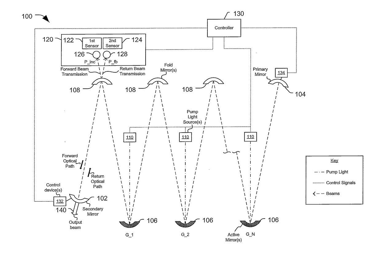
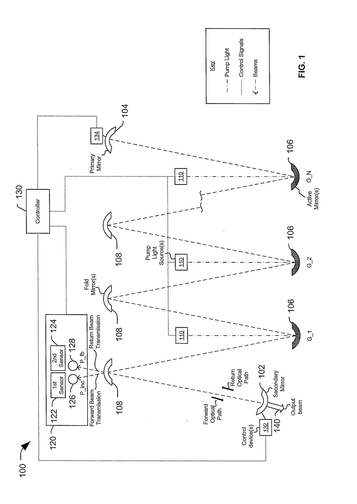
[0014]FIG. 1 illustrates a particular embodiment of a laser resonator system 100. The laser resonator system 100 illustrated in FIG. 1 is shown as an unstable thin disk laser resonator system. However, in other embodiments, other laser resonator systems may be used, such as a slab resonator system as illustrated in FIG. 3. In FIG. 1, the laser resonator system 100 includes a secondary mirror 102 (also known as an output coupler). The secondary mirror 102 is configured to reflect a first portion of light (e.g., a beam) received at the secondary mirror 102 along a return optical path toward a primary mirror 104 of the laser resonator system 100. The secondary mirror 102 is also configured to allow a second portion of the light received at the secondary mirror 102 to pass through...


PUM


Abstract

A device includes a first sensor configured to generate a first output signal corresponding to an energy of a portion of a forward beam transmitted by a mirror of a laser resonator system. The device further includes a second sensor configured to generate a second output signal corresponding to an energy of a portion of a return beam transmitted by the mirror. A ratio of the energy of the portion of the forward beam and the energy of the portion of the return beam corresponds to a measurement of a feedback ratio of the laser resonator system.

Description

FIELD OF THE DISCLOSURE[0001]The present disclosure relates to an energy ratio sensor for use in laser resonator systems.BACKGROUND[0002]Certain types of laser systems, such as unstable laser resonators, can be useful to generate high power laser output but can be difficult to control and monitor. For example, in a laser resonator system, light beams are reflected along optical paths at the same time that the light beams are amplified (e.g., energy of the light beams is increased). A portion of the light beams may be output from the laser resonator system, while another portion of the light beams is reflected back into the laser resonator system. Output power of the laser resonator system may not provide an accurate estimate of power of light beams reflected within the laser resonator system. Although components of the laser resonator system may be designed to reflect or transmit high power light beams, the components are not perfectly reflective or transmissive. Absorbing only a po...

Claims


Application Information

Patent Timeline
Patent Type & Authority Applications(United States)
IPC IPC(8): H01S3/13H01S3/0941H01S3/06H01S3/16H01S3/08H01S3/081
CPCH01S3/1305H01S3/08059H01S3/0813H01S3/08095H01S3/0941H01S3/0604H01S3/1618H01S3/1643H01S3/0606H01S3/07H01S3/08081H01S3/09408H01S3/1312H01S3/139H01S3/0014H01S3/0817H01S3/136G02B26/08H01S3/0818H01S3/105H01S3/10015
Inventor GYLYS, VYTAS T.KOUMVAKALIS, ANDREANEEDHAM, GREGORY A.HOLMES, DALE A.
Owner THE BOEING CO
Why Eureka
Try Eureka