Unmanned aerial vehicle rotor system

A technology for aircraft rotors and helicopter rotors, applied in the field of UAV rotor systems, can solve problems such as being unsuitable for medium-sized UAVs, complex swash plate structure, inconvenient disassembly and maintenance, etc., to achieve stable and efficient output and facilitate fault diagnosis. , the effect of easy maintenance

Pending Publication Date: 2019-05-03
一飞智控(天津)科技有限公司
View PDF0 Cites 0 Cited by
  • Summary
  • Abstract
  • Description
  • Claims
  • Application Information

AI Technical Summary

Problems solved by technology

[0003] First, small unmanned helicopters are limited by the rotor space, and most of them adopt the off-axis control method, which will cause the disadvantages of complex external structure, large system weight, low force transmission efficiency, etc. Big
[0004] Second, the swash plate of traditional unmanned helicopters with periodic variable pitch has a complex structure, generally composed of universal bearings and other accessories, but it is difficult to manufacture and assemble, the production cost is high, and it is not

Method used


Image

  • Unmanned aerial vehicle rotor system
  • Unmanned aerial vehicle rotor system
  • Unmanned aerial vehicle rotor system

Examples


Embodiment 1

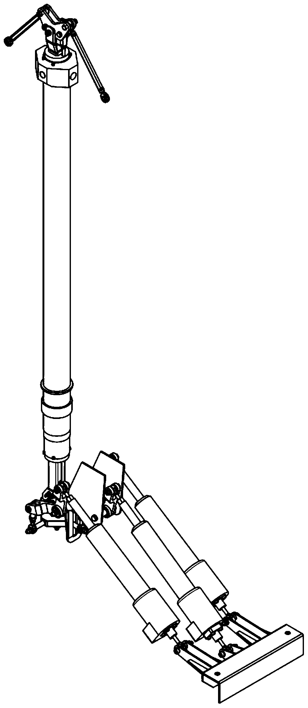
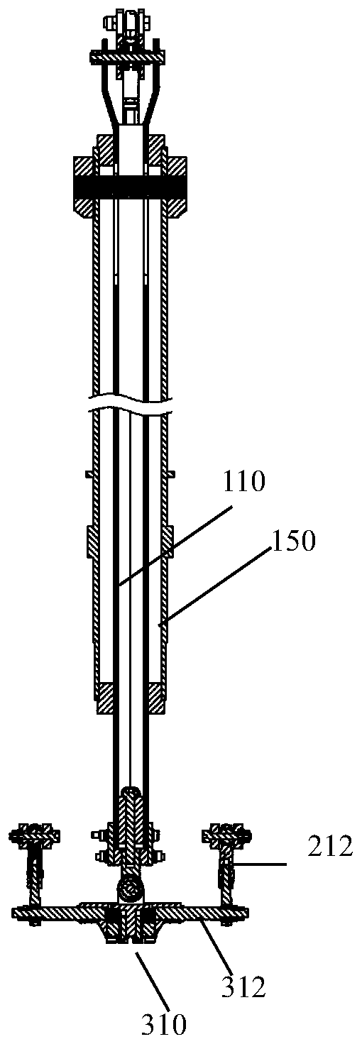
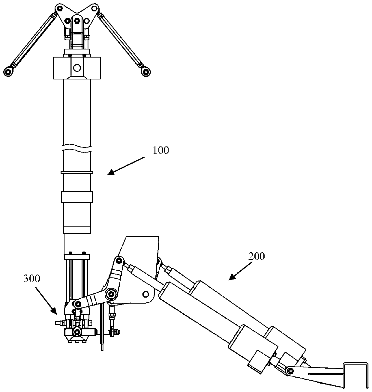
[0041] A UAV rotor system of the present invention includes a seesaw UAV rotor and a rotor control device, and the rotor control device includes a swash plate assembly 300 and a total moment slider assembly 100,

[0042] The swash plate assembly includes a swash plate 310, a swash plate rotation shaft 311 rotatably set in the swash plate, and the swash plate arm 312, 313, the total moment sliding bar assembly includes the central joint bearing 111 arranged at the lower end of the total moment sliding bar 110, corresponding to the side joint bearing 121 arranged at the lower end of the long tie rod 120, the central joint bearing 111 and the side joint bearing 121 The ball head is fixedly connected to the rotation axis of the swash plate through a horizontal connecting rod 314, and the horizontal connecting rod is arranged parallel to the support arm of the swash plate in the pitch direction. That is, the maximum angle that can be realized by the ball head of the joint bearing, ...

Embodiment 2

[0053] As a specific embodiment, the fixed end of the linear steering gear is connected to the body through a joint bearing, and the output end of the linear steering gear is connected to the L-shaped control arm through a joint bearing. Further, it also includes a steering gear drive assembly, the steering gear drive assembly includes three linear steering gears 210 whose tail ends are rotatably connected to the body, three corresponding to the linear steering gears and one end connected to the The output end of the linear steering gear is hinged and the middle part is rotatably connected to the L-shaped control arm 211 of the body;

[0054] When installing the fixed end of the linear steering gear, first connect the fixed end of the linear steering gear to the mounting part of the steering gear through bolts, then connect the mounting part of the steering gear to the joint bearing through threads, and finally fix the joint bearing to the installation position of the body with...

Embodiment 3

[0063] Wherein, the paddle clamp assembly includes a paddle clamp and a torque converter arm, and the paddle clamp includes a connecting cylinder that is rotatably connected with the propeller hub support arm, and is integrally formed with the connecting cylinder Or fixedly connected paddle clips, the torque converter arm is fixedly connected with the connecting cylinder, the connecting cylinder and the distance ring of the paddle clip are fixed in the axial direction through bolted connection, and the distance between the paddle clip is fixed The ring is rotatably arranged on the arm of the propeller hub through the bearing, and the torque conversion adjustment can be realized by adjusting the spacer ring of the propeller clip. The upper end of the total moment sliding rod is connected to the butterfly member through joint bearings, and both sides of the butterfly member are connected to the upper end of the long tie rod through joint bearings.

[0064] Specifically, the padd...


PUM


Abstract

The invention discloses a rotor system of an unmanned aerial vehicle. The UAV rotor system comprises a helicopter rotor wing control device and a seesaw type rotor wing. The helicopter rotor wing control device comprises an inclined disc assembly and a total-moment sliding rod assembly; the inclined disc assembly comprises an inclined disc, a rotor wing shaft is tubular, a total-moment sliding rodand a long pull rod penetrate through the rotor wing shaft, and the upper end is in corresponding transmission connection with a propeller clamp assembly. A steering engine driving assembly, the inclined disc assembly and the total-moment sliding rod assembly are in modular design, so the structural complexity is reduced, and operation such as design, debugging and maintenance of the rotor systemis simplified. Three linear steering engines of the steering engine driving assembly of the rotor wing control system are used in parallel, the space utilization rate is increased, and the structuralcomposition is simplified.

Description

technical field [0001] The invention belongs to the technical field of unmanned aerial vehicles, and in particular relates to an unmanned aerial vehicle rotor system. Background technique [0002] UAV flight control system, including multi-rotor UAV flight control system and fixed-wing unmanned helicopter flight control system. It is mainly used in the field of plant protection, power line inspection, geographical survey, logistics and transportation and other fields. A complete set of controls for unmanned helicopter flight. Including total moment, longitudinal, lateral and heading four control systems. The total moment control system can change the size of the rotor pull to control the helicopter's ascent and descent. The longitudinal and lateral control system can change the direction of the rotor pulling force in space to control the longitudinal and lateral displacement, pitch and roll motion of the helicopter. The heading control system can change the push (pull) f...

Claims


Application Information

Patent Timeline
IPC IPC(8): B64C39/02B64C27/43
Inventor 刘帅孙涛贾良现
Owner 一飞智控(天津)科技有限公司
Why Eureka
Try Eureka