
A haptic feedback device

a haptic feedback and feedback technology, applied in the field of haptic feedback devices, can solve the problems of difficult to provide actuators, low selectivity of neural interfaces, and serious functional limitations, and achieve the effect of convenient put on and worn, and easy to be put on and worn

Inactive Publication Date: 2017-05-04
SCUOLA SUPERIORE S ANNA
View PDF4 Cites 17 Cited by
  • Summary
  • Abstract
  • Description
  • Claims
  • Application Information

AI Technical Summary

Benefits of technology

The invention provides a device that allows someone to easily recognize the contact of their prosthetic or sensory-deficient limb with an object, without needing to use their brain too hard. This device can be easily worn and can help the user recognize movements of their prosthesis or limb, as well as any displacements of objects caused by the prosthesis or limb.

Problems solved by technology

The loss of a limb causes serious functional limitations, typically in the ability of handling objects and of walking.
However, it is difficult to provide actuators that have suitably small size, weight and energy requirements, moreover the available neural interfaces have a low selectivity and a short duration, which makes this approach unsuccessful.
However, the above devices the drawback of accustoming the user to a continuous stimulation during the contact steps, or in any case when using the prosthesis.
This complicates the recognition of the events and can tire the patient.
Furthermore, most prior art haptic feedback devices consume a large amount of energy to generate the tactile stimulations.
To ensure a certain autonomy relatively heavy and bulky batteries are therefore required, which cause discomfort to the patient.

Method used


Image

  • A haptic feedback device
  • A haptic feedback device
  • A haptic feedback device

Examples


Embodiment Construction

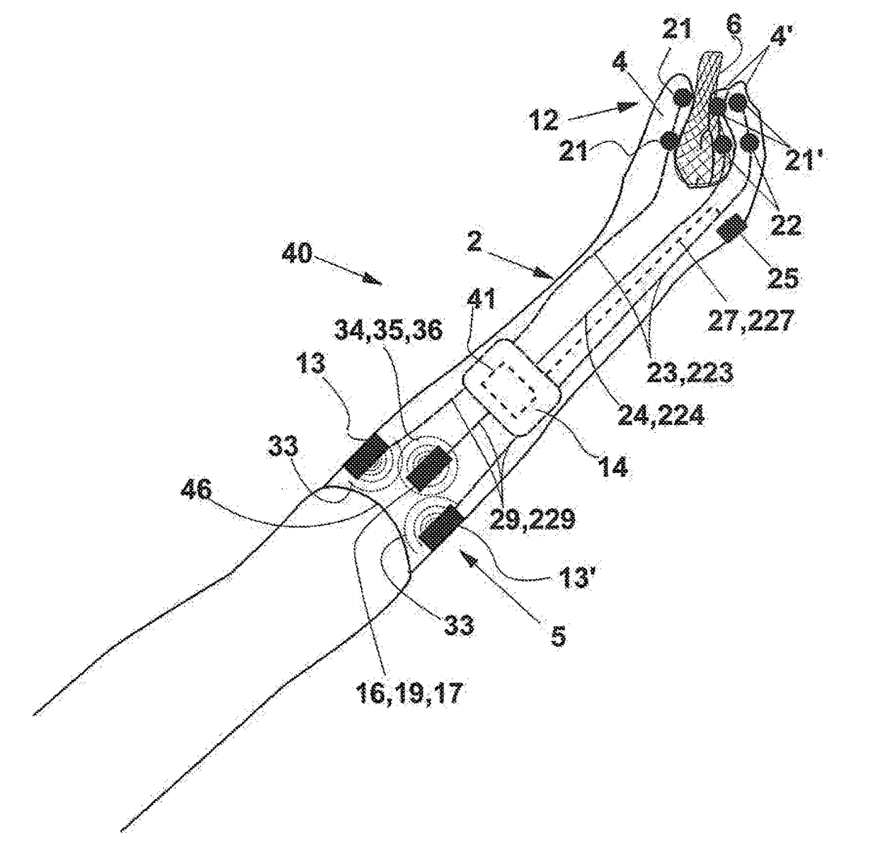
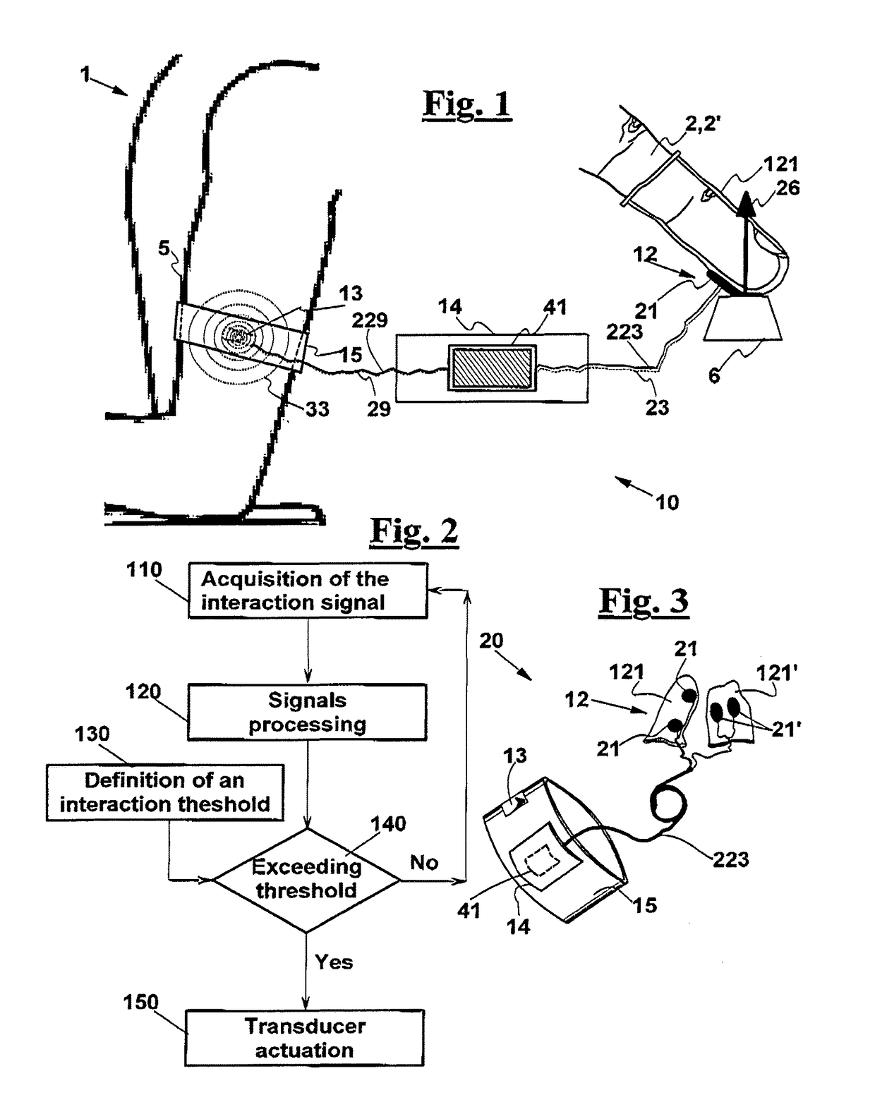
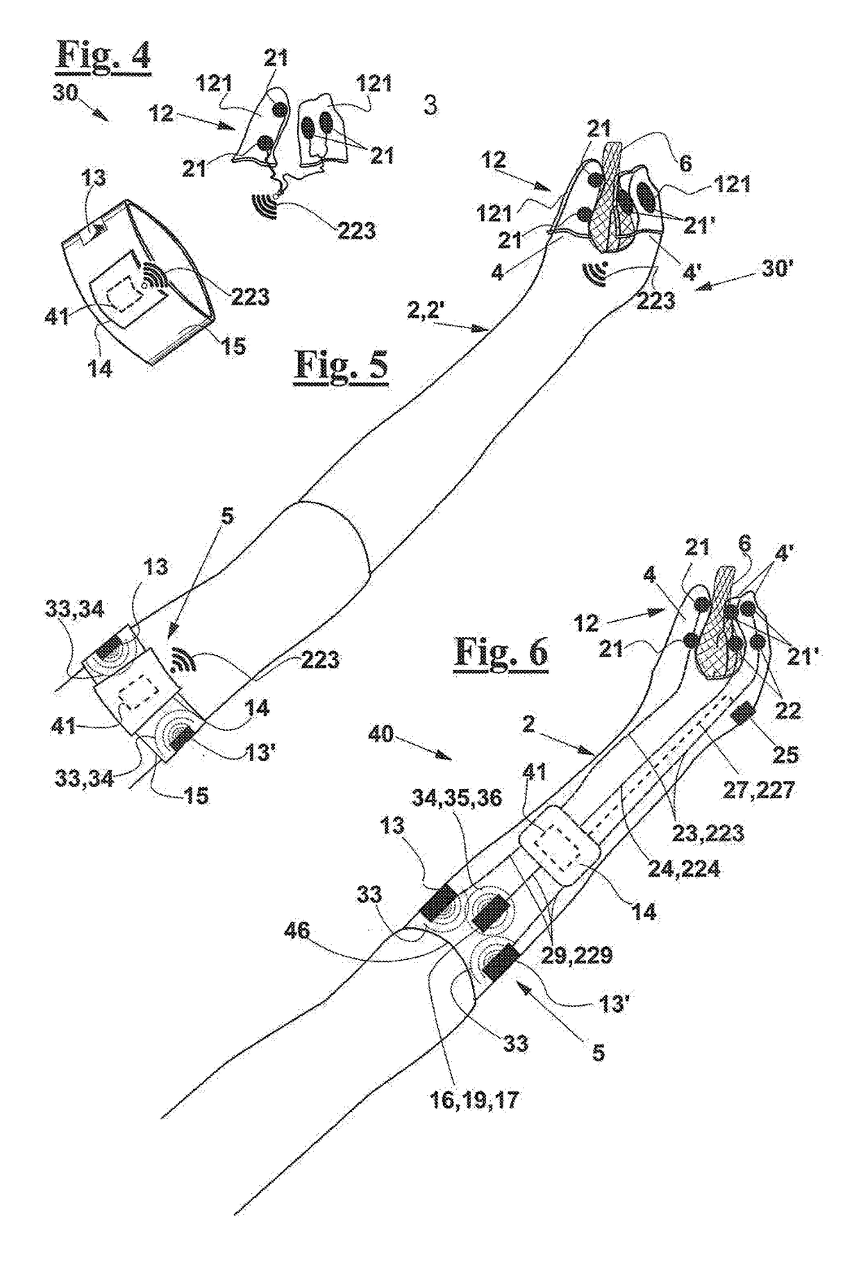
[0087]With reference to FIG. 1, a haptic feedback device 10 is described, according to the invention, for a user 1. The device is adapted to a user of a prosthetic body part 2, in this case a prosthetic portion of an upper limb such as a prosthetic finger, or for a user who is sensorially deficient at such a body part 2′, for example due to a spinal lesion or an ictus.

[0088]Device 10 comprises a sensor interface 12 equipped with at least one contact sensor 21. In this case, sensor interface 12 comprises a thimble 121 having at least one contact sensor 21 that is able to generate a contact signal 23, typically an electric signal, when sensor 21 receives an input 26 from an object 6, due to a contact or to a pressure that user 1 applies on object 6. For example, according to the sensor 21 type, input 26 can be a heat flux or an energy flux associated with an electromagnetic field or with a compression wave.

[0089]Sensor thimble 121 is worn on finger 2,2′, which can be a finger 2 of a p...


PUM


Abstract

A haptic feedback device (10) for a prosthetic body part (2) or a sensorially deficient body part (2′) comprises a sensor interface (12) configured to be arranged on the prosthetic or sensorially deficient body part (2,2′), equipped with a contact sensor (21) to generate a contact signal (23) according to a contact condition with an object (6); a tactile stimulation unit equipped with a transducer (13,13′) to generate a tactile stimulation (33); a support (15) wearable on a sensorially sound body part (5), on which the tactile stimulation unit is arranged, so as to receive the stimulation (33); a control unit (14) for receiving the contact signal (23) from the contact sensor (21) and comprising a program means (41) configured to cause a control signal (29) to be produced for actuating the transducer, responsive to the contact signal (23), and for cyclically comparing the contact signal (23) with a contact threshold value (Ti,j); for producing the control signal (29) and actuating the transducer (13,13′) when the contact signal (23,23′) crosses the threshold value (Ti,j); for leaving the transducer (13,13′) still in an intermediate time between this crossing of the threshold (Ti,j) and a subsequent crossing in an opposite direction, so that the transducer (13) is actuated if an event occurs of beginning or of end of a contact between the prosthetic or sensorially deficient body part (2,2′) and the object (6).

Description

FIELD OF THE INVENTION[0001]The present invention relates to a haptic device for providing a haptic feedback to a user of a prosthetic a body part, or to a user who has a sensorially deficient body part, for example due to an ictus, or to a spinal column trauma, and so on.[0002]More in detail, the invention relates to a device for providing a haptic feedback to the user, in connection to an interaction with an external object, such as contacting, gripping, or displacing this object.STATE OF THE ART[0003]The loss of a limb causes serious functional limitations, typically in the ability of handling objects and of walking. These limitations are often partially compensated for by myoelectric prosthesis, which can more and more closely approximate the natural limb movements.[0004]Myoelectric prosthesis are controlled by a closed loop technique that normally exploits a visual feedback, which allows the user, for example, to check whether a gripping process is being correctly performed or ...

Claims


Application Information

Patent Timeline
Patent Type & Authority Applications(United States)
IPC IPC(8): A61F2/76A61F2/68
CPCA61F2/76A61F2/68A61F2002/764A61F2002/7635A61F2002/7665A61F2002/6827A61F2/70
Inventor CIPRIANI, CHRISTIANCLEMENTE, FRANCESCOD'ALONZO, MARCOEDIN, BENONI B.
Owner SCUOLA SUPERIORE S ANNA
Learn More