Adjustable Stroke Mechanism for Random Orbital Machine

a random orbital machine and stroke mechanism technology, which is applied in the direction of grinding drives, cranks, manufacturing tools, etc., can solve the problems of not being able to remove surface defects, requiring more skill and control of the machine than a typical hobbyist, and scratch removal

Active Publication Date: 2017-05-04
LAKE COUNTRY TOOL LLC
View PDF18 Cites 9 Cited by
  • Summary
  • Abstract
  • Description
  • Claims
  • Application Information

AI Technical Summary

Problems solved by technology

Removing scratches, however, requires more skill and control of the machine than a typical hobbyist possesses.
Small stroke machines typically only polish the paint and do not cut into it, and, therefore, are not able to remove surface defects.
There are also longevity issues associated with increased RPM for the motor and increased OPM for the pad.

Method used


Image

  • Adjustable Stroke Mechanism for Random Orbital Machine
  • Adjustable Stroke Mechanism for Random Orbital Machine
  • Adjustable Stroke Mechanism for Random Orbital Machine

Examples


first embodiment

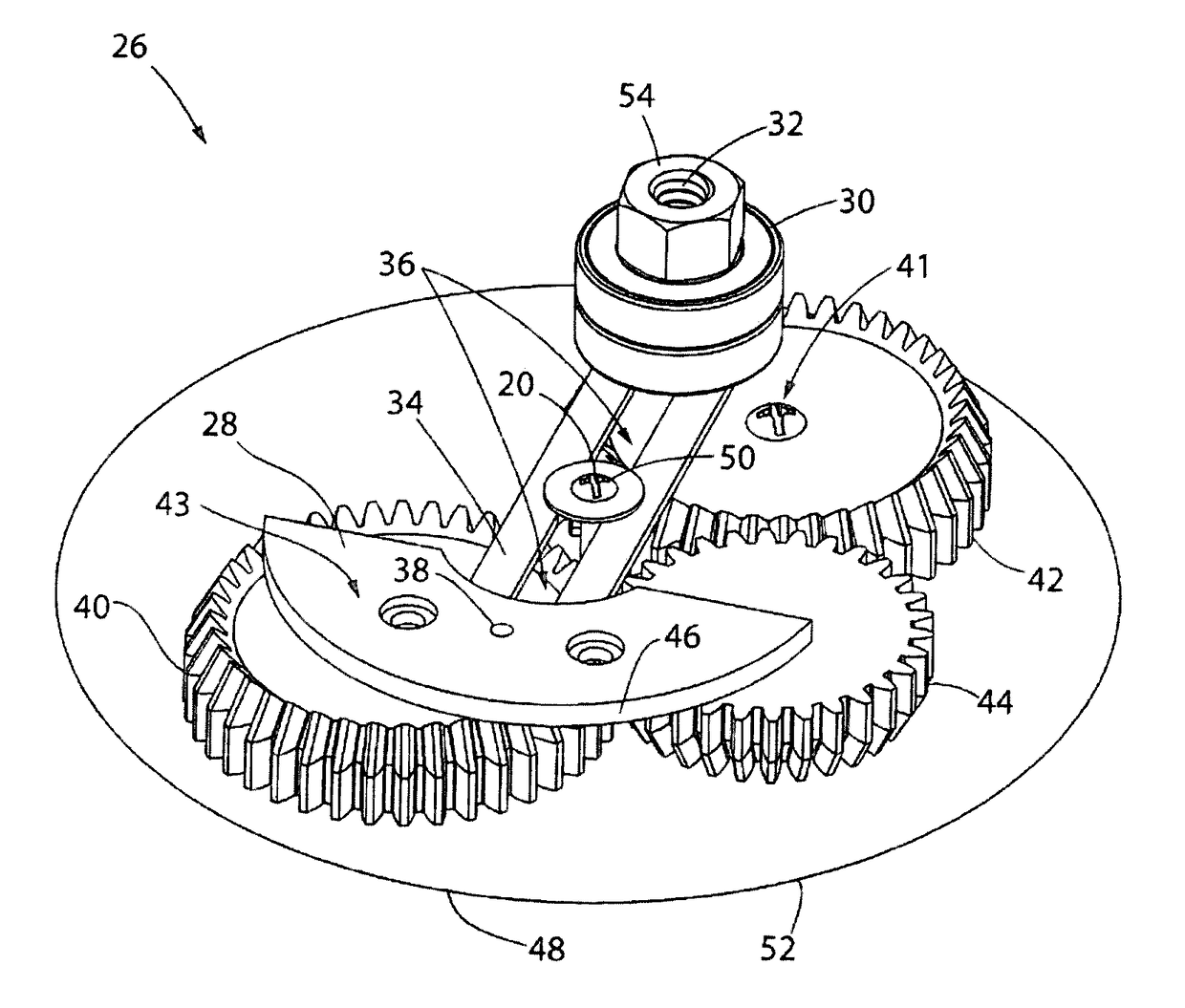
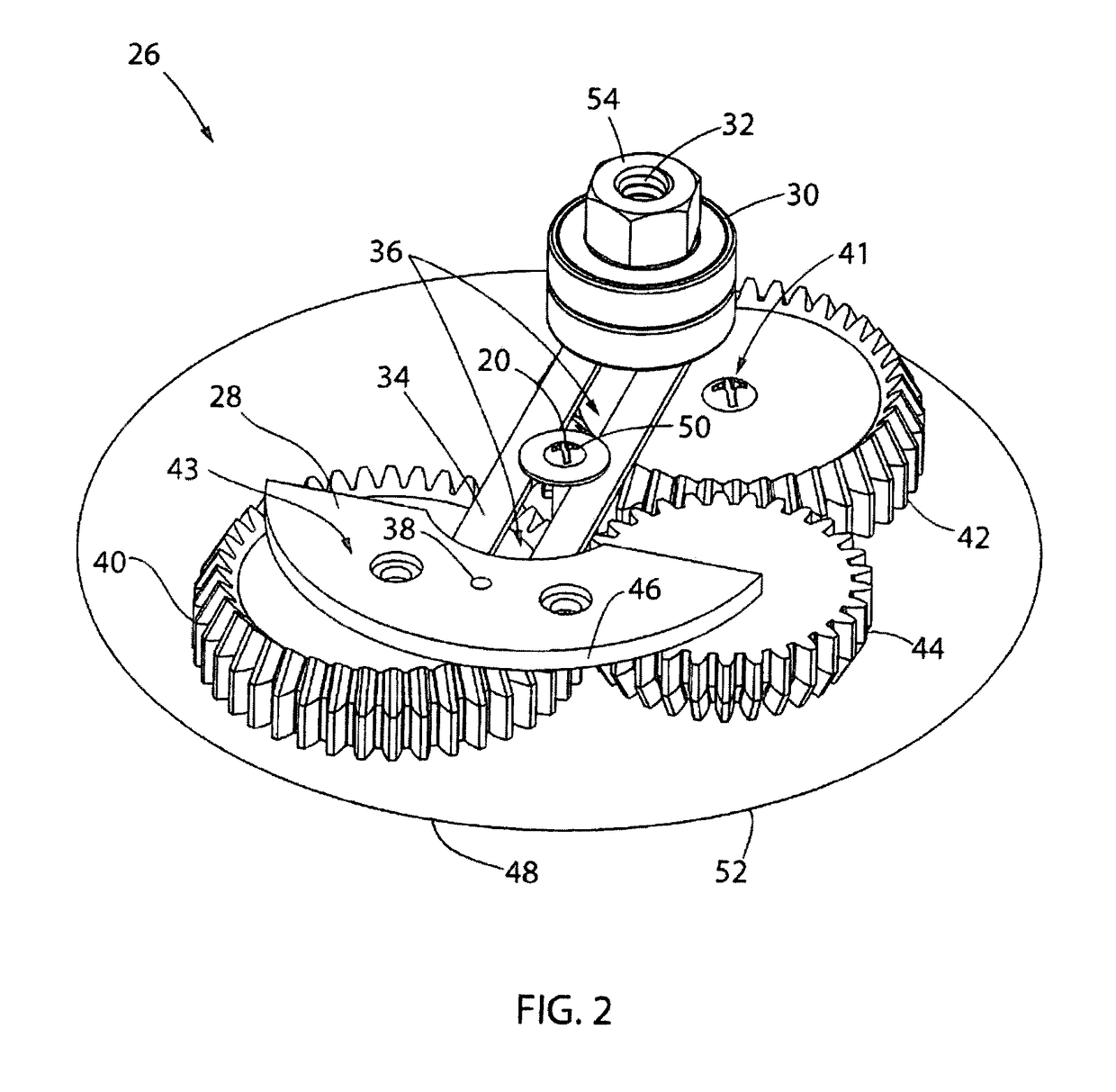
[0056]Moving on to FIG. 2, an adjustable stroke mechanism 26 is shown. The adjustable stroke mechanism 26 utilizes a series of gears to allow the backing plate mount 54 and counterweight 28 to automatically move toward or away from one another as any one of the gears is rotated. These synched movements of the backing plate mount 54 and the counterweight 28 allow the offset, or stroke, of a random orbital machine 10 to be adjusted while keeping vibrations in check. The offset may be adjusted between a maximum and minimum setting, or be adjustable by choosing a series of pre-selected settings.

[0057]A shroud will enclose the adjustable stroke mechanism 26 and is represented by a proposed shroud perimeter 48. The shroud would function much as the shroud 12 shown in FIG. 1 and will enclose the components of the adjustable stroke mechanism 26. The proposed shroud curvature 52 may also be matched to the counterweight curvature 46 such that the counterweight 28 will not intersect the propos...

second embodiment

[0065]Transitioning now to FIG. 6, an adjustable stroke mechanism 60 is shown. The adjustable stroke mechanism 60 is represented within the perimeter of a shroud 48, similar to the known random orbital machine 10 in FIG. 1. The proposed shroud perimeter 48 also has a proposed shroud curvature 52 that houses the entire adjustable stroke mechanism 60. The entire adjustable stroke mechanism 60 rotates within the proposed shroud perimeter 48 when the random orbital machine 10 is activated by depressing the switch 7.

[0066]A fully extended stroke 74 is shown in FIG. 6. The stroke radius 22 is shown by the offset of the backing plate mount 54 to the rotational axis 20 of the backing plate mount 54. The counterweight 28 balances out the backing plate mount 54 such that minimal vibrations are experienced when the adjustable stroke mechanism 60 is activated.

[0067]The stroke radius 22 is adjusted by movement of a first rack gear 66, a second rack gear 68, a first pinion gear 62, and a second p...

third embodiment

[0070]Referring now to FIG. 8, an adjustable stroke mechanism 100 is shown in an exploded perspective view in order to show the various components within the adjustable stroke mechanism 100. The adjustable stroke mechanism 100 includes a housing 102 having a wall 104 surrounding a cavity 106. As shown in FIG. 8, the wall 104 is depicted as circular in shape; however, the wall 104 could be in the form of any number of shapes. In addition, the housing 102 includes a top plate 108 oriented perpendicular to the wall 104, which provides an upper limit to the cavity 106. The housing 102 also includes a housing cover 110 oriented perpendicular to the wall 104 and opposite the top plate 108, which provides a lower limit to the cavity 106. The wall 104 of the housing 102 has a plurality of apertures 112 formed therein. While FIG. 8 shows two (2) apertures 112 formed in the wall 104, it is contemplated that either more or less than two (2) apertures 112 may be formed in the wall 104.

[0071]An ...


PUM

PropertyMeasurementUnit
timeaaaaaaaaaa
pressureaaaaaaaaaa
stroke diameteraaaaaaaaaa

Abstract

An adjustable stroke mechanism for a random orbital machine including a housing having a wall enclosing a cavity, an adjuster ring surrounding the housing and having a first set of gear teeth along a first portion of an inner surface, and a second set of gear teeth along a second portion of the inner surface, a counterweight having gear teeth on an exterior surface disposed within the housing, and a bearing carriage having gear teeth disposed within the housing. At least one counterweight gear that meshes with the gear teeth of the counterweight and the first set of gear teeth of the adjuster ring, and at least one bearing carriage gear that meshes with the gear teeth of the bearing carriage and the second set of gear teeth of the adjuster ring, so that movement of the adjuster ring causes movement of both the counterweight and the bearing carriage.

Description

CROSS-REFERENCE TO RELATED APPLICATIONS[0001]This application claims priority to U.S. provisional application No. 62 / 249,521, filed on Nov. 2, 2015, and U.S. provisional application No. 62 / 340,335, filed on May 23, 2016, the entire contents of which are both hereby expressly incorporated by reference into this application.BACKGROUND OF THE INVENTION[0002]1. Field of the Invention[0003]The present invention relates to a method and apparatus for adjusting the stroke on a random orbital machine, such as, but not limited to, polishing machines and sanding machines. This adjustment ability allows a user to define the stroke of the random orbital machine and adjust it between a maximum definitive stroke setting and minimum zero orbit setting.[0004]2. Discussion of the Related Art[0005]Polishing machines and sanding machines are routinely used in the automotive detailing industry and home building industry to correct imperfections in the paint or drywall and to apply polishes and waxes. Th...

Claims


Application Information

Patent Timeline
Patent Type & Authority Applications(United States)
IPC IPC(8): B24B23/02B24B47/10
CPCB24B47/10B24B23/02B24B23/028B24B23/03B24B23/04B24B47/12F16C3/28B24B41/042F16C2322/50
Inventor MCLAIN, SCOTT S.SNYKER, MARK
Owner LAKE COUNTRY TOOL LLC
Why Eureka
Try Eureka