Vehicle control apparatus, vehicle control method, and vehicle control program

a vehicle control and vehicle technology, applied in vehicle position/course/altitude control, process and machine control, instruments, etc., can solve the problem of inability to move the vehicle to a predetermined position at a desired timing, and achieve the effect of increasing the responsiveness of the devi

Active Publication Date: 2017-05-04
HONDA MOTOR CO LTD
View PDF0 Cites 20 Cited by
  • Summary
  • Abstract
  • Description
  • Claims
  • Application Information

AI Technical Summary

Benefits of technology

[0017]According to aspect (1), (6), or (7), it is possible to move the vehicle to a desired position at a desired timing because the target speed of the own vehicle is corrected on the basis of the difference between the position of the own vehicle for each predetermined time in the future and the current position of the own vehicle.
[0018]According to aspect (2) or (3), it is possible to more precisely move the vehicle to a desired position at a desired timing because the target speed of the own vehicle is corrected on the basis of the difference between the position of the own vehicle for each predetermined time in the future and the current position of the own vehicle based on the target speed.
[0019]According to aspect (4), it is possible to increase responsiveness of a device of a control target because a time phase is advanced and the target speed is calculated on the basis of a primary target speed for each position on the trajectory.
[0020]According to aspect (5), it is possible to prevent an own vehicle M from arriving at a position of a lane change before (or after) a predetermined schedule because the target speed is corrected when the own vehicle changes lanes.

Problems solved by technology

However, in the conventional technology, it may be impossible to move the vehicle to a predetermined position at a desired timing.

Method used


Image

  • Vehicle control apparatus, vehicle control method, and vehicle control program
  • Vehicle control apparatus, vehicle control method, and vehicle control program
  • Vehicle control apparatus, vehicle control method, and vehicle control program

Examples


first embodiment

[0036][Vehicle configuration]

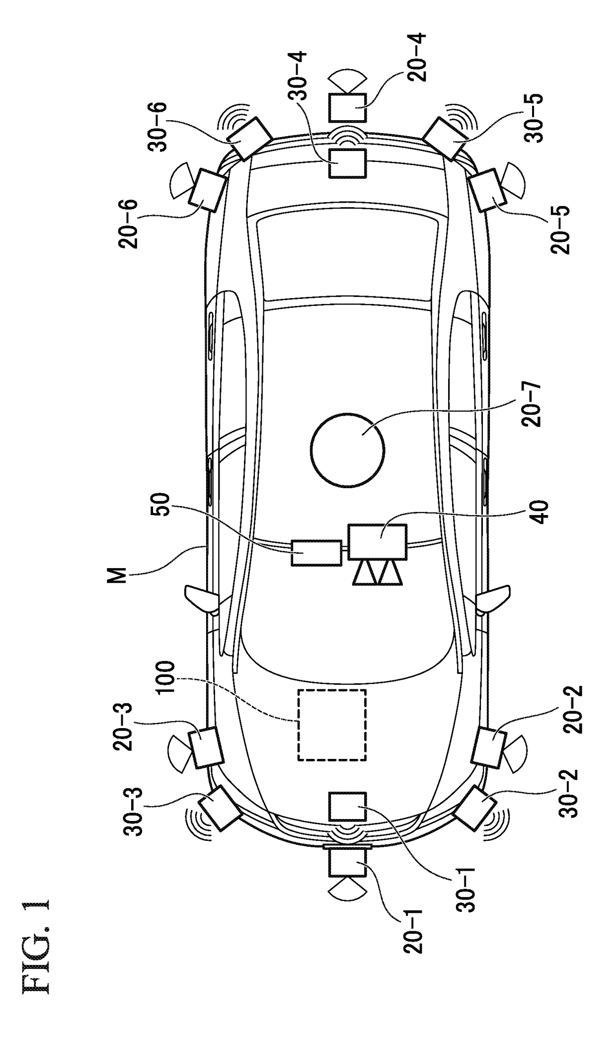
[0037]FIG. 1 is a diagram illustrating components provided in a vehicle (hereinafter referred to as an own vehicle M) equipped with a vehicle control apparatus 100 according to the first embodiment. The vehicle equipped with the vehicle control apparatus 100 is, for example, a vehicle with two wheels, three wheels, four wheels, or the like and includes a vehicle having an internal combustion engine such as a diesel engine or a gasoline engine as a power source, an electric vehicle having an electric motor as a power source, a hybrid vehicle having both an internal combustion engine and an electric motor, etc. Also the above-mentioned electric vehicle is driven using power discharged by, for example, a cell such as a secondary cell, a hydrogen fuel cell, a metal fuel cell, or an alcohol fuel cell.

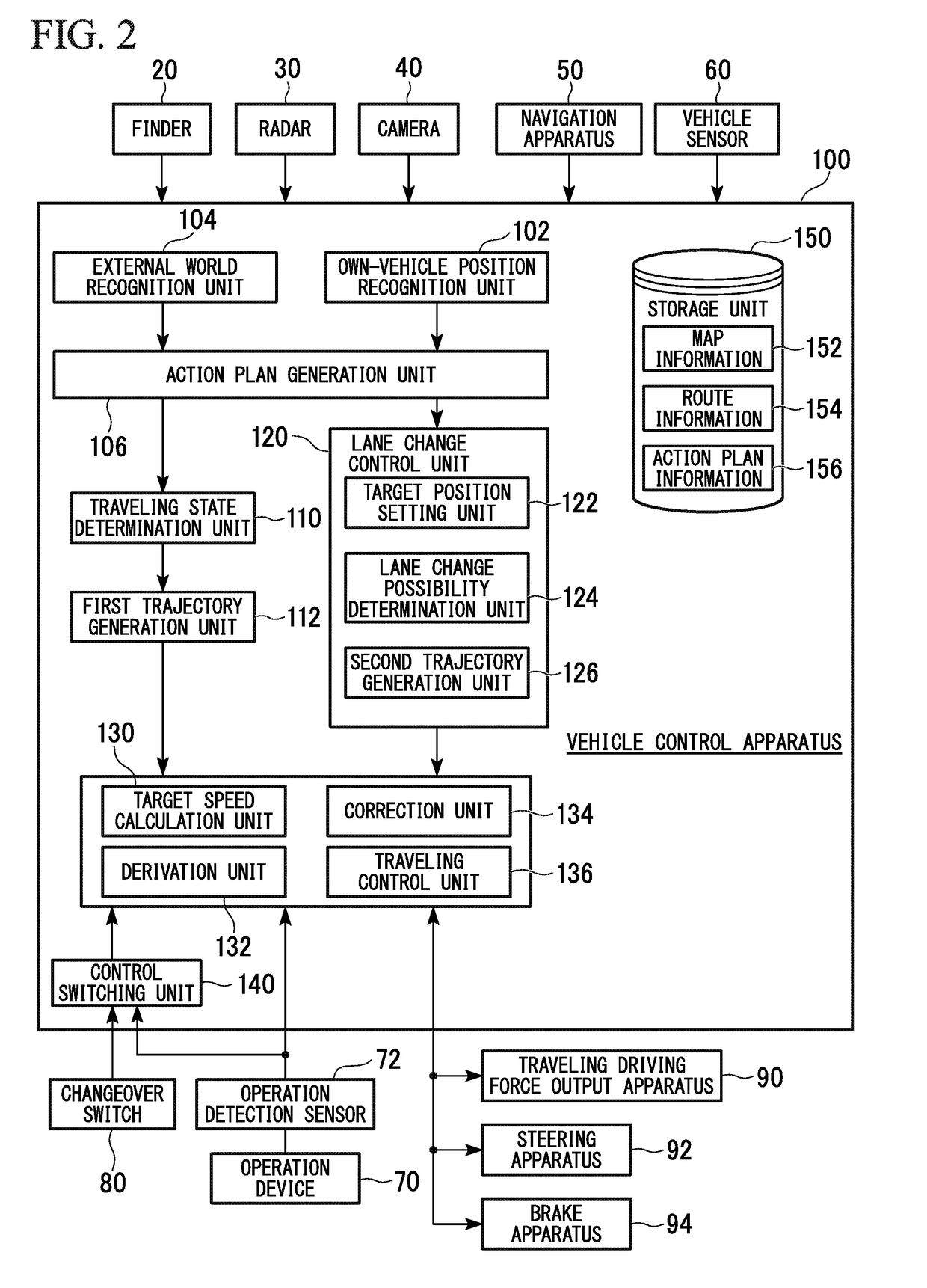
[0038]As illustrated in FIG. 1, sensors such as finders 20-1 to 20-7, radars 30-1 to 30-6, and a camera 40, a navigation apparatus 50, and the above-mentioned ve...

second embodiment

[0109]Hereinafter, the second embodiment will be described. The vehicle control apparatus 100 in the second embodiment is different from that in the first embodiment in that the secondary target speed vs is corrected on the basis of an amount of shift (hereinafter, a predicted difference) when a predicted arrival position of the own vehicle M when the own vehicle M travels at the secondary target speed vs is shifted before / after the target position K. Hereinafter, the related difference will be mainly described.

[0110]The derivation unit 132 in the second embodiment derives a predicted difference between a predicted arrival position Q of the own vehicle M and the target position K on a trajectory generated by the first trajectory generation unit 112 or the second trajectory generation unit 126 predicted to be generated after the passage of the predetermined time Δt when the own vehicle M travels on the basis of the secondary target speed vs calculated by the target speed calculation ...


PUM


Abstract

A vehicle control apparatus includes a trajectory generation unit configured to generate a locus of a position of an own vehicle for each predetermined time in a future as a trajectory of the own vehicle, a target speed calculation unit configured to calculate a target speed of the own vehicle for each position on the trajectory generated by the trajectory generation unit, a traveling control unit configured to control traveling of the own vehicle on the basis of the target speed calculated by the target speed calculation unit, a derivation unit configured to derive a difference between a position on the trajectory generated by the trajectory generation unit and a current position of the own vehicle every time the predetermined time elapses, and a correction unit configured to correct the target speed calculated by the target speed calculation unit on the basis of the difference derived by the derivation unit.

Description

CROSS REFERENCE TO RELATED APPLICATIONS[0001]Priority is claimed on Japanese Patent Application No. 2015-212112, filed Oct. 28, 2015, the content of which is incorporated herein by reference.BACKGROUND OF THE INVENTION[0002]Field of the Invention[0003]The present invention relates to a vehicle control apparatus, a vehicle control method, and a vehicle control program.[0004]Description of Related Art[0005]Research on technology for automatically driving a vehicle such as a four-wheeled vehicle has recently progressed.[0006]In relation to this technology, there is a driving assistance device including an instruction means for issuing an instruction for starting automatic driving according to an operation of a driver, a setting means for setting a destination of the automatic driving, a determination means for determining a mode of the automatic driving according to whether a destination has been set when the driver operates the instruction means, and a control means for controlling th...

Claims


Application Information

Patent Timeline
Patent Type & Authority Applications(United States)
IPC IPC(8): B60W30/14
CPCB60W30/143B60W2550/302B60W2550/306B60W2720/10B60W2520/10B60W30/18163B60W50/0097B60W30/095B60W2050/0011G08G1/167G08G1/00B60W30/12B60W30/16G05D1/0212
Inventor ONIWA, YOSHIHIROYOSHIDA, MINEYUKI
Owner HONDA MOTOR CO LTD
Why Eureka
Try Eureka