
Testing head comprising vertical probes

Inactive Publication Date: 2017-05-04
TECHNOPROBE
View PDF4 Cites 1 Cited by
  • Summary
  • Abstract
  • Description
  • Claims
  • Application Information

AI Technical Summary

Benefits of technology

The testing head in this patent is designed to make sure there is a proper connection between the device being tested and the testing head, and to also have a long lifespan. The testing head has multiple probes that have a deformed part between them, which is shaped like a tip and is designed to make a lot of connections. This design helps to reduce wear and tear on the testing head, while still ensuring a good connection with the device being tested.

Problems solved by technology

However, the height of that protruding part is limited by the probe fragility and it is normally between 300 and 500 μm.
Actually, that vertical movement value of the probes is reachable only theoretically, since already under much smaller movements, problems arise, which problems are related to the probes getting stuck in the guide holes, particularly in the lower guide holes, and to the permanent deformation of the probes.
Those probes guarantee an almost total exploitation in terms of vertical movement of the probe part protruding from the lower guide, but they have a considerable realization as well as maintenance complexity.
Moreover, the lower guide presence considerably limits the possibility of horizontal movement of the probe tip; in fact that movement strictly depends on the difference between the hole diameter and the probe diameter.
However, although that known solution is advantageous from different points of view, it has important drawbacks, the first being the imperfect alignment of the probe contact tips of the testing head with respect to the contact pads of a device under test, exactly due to the presence of the pre-deformed section; particularly, that imperfect alignment causes a shortening of the working life of the probes and thus of the testing head.
Furthermore, the realization of the pre-deformed section of the contact probes requires using complicated photolithographic techniques, with a consequent rise in the manufacturing costs of the contact probes and thus of the overall testing head.

Method used


Image

  • Testing head comprising vertical probes
  • Testing head comprising vertical probes
  • Testing head comprising vertical probes

Examples


Embodiment Construction

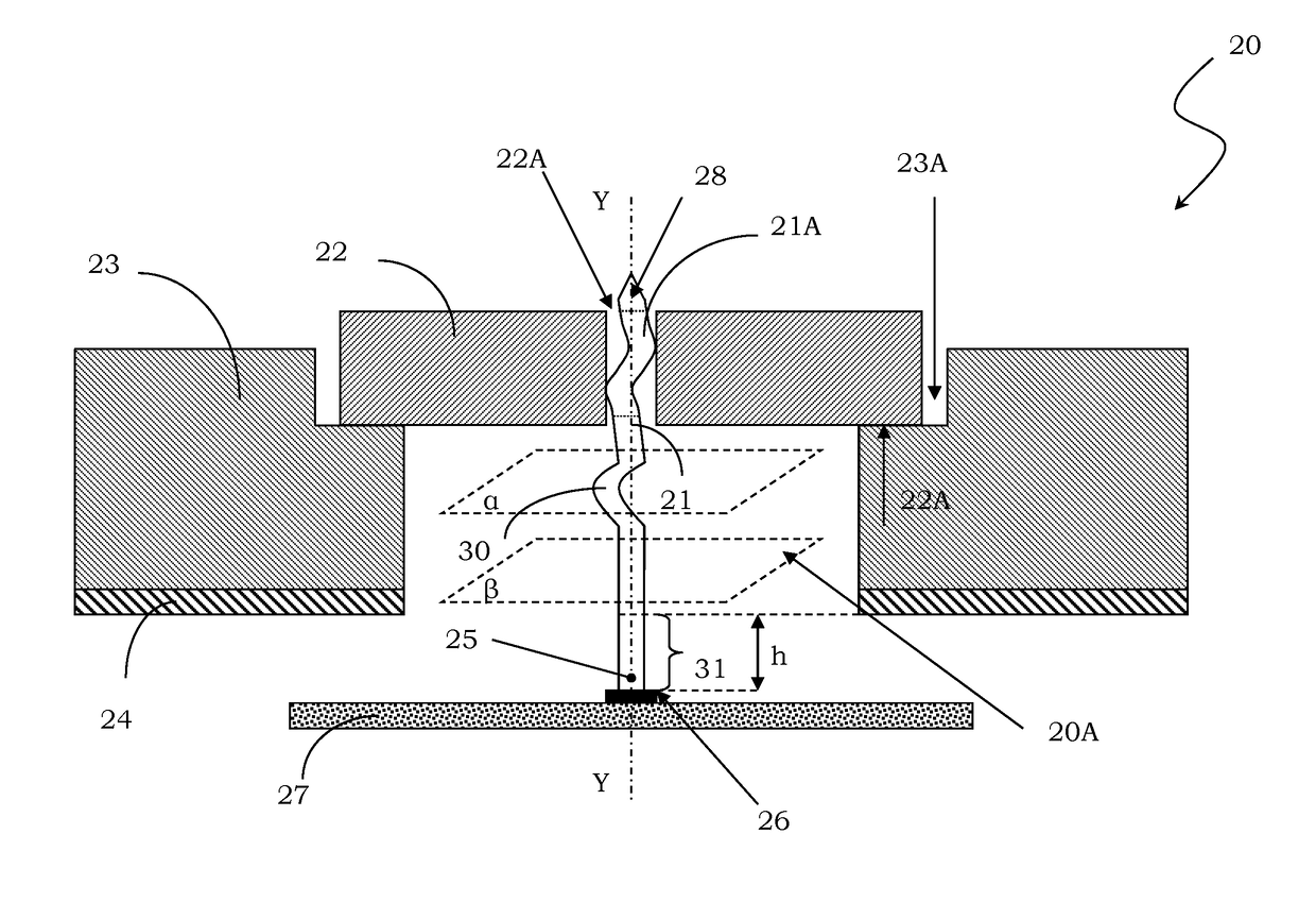
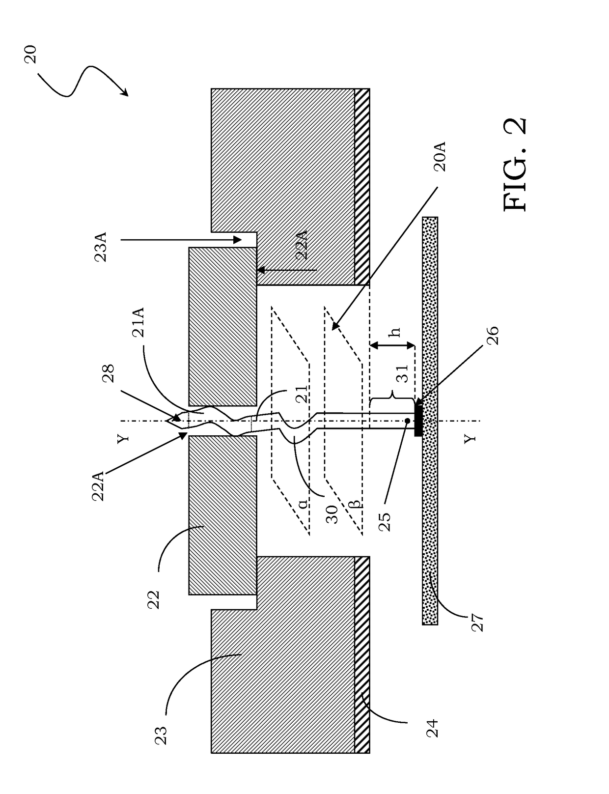
[0070]With reference to those figures, and particularly to FIG. 2, a testing head according to an embodiment of the disclosure is schematically shown and globally indicated with 20.

[0071]It should be noted that the figures represent schematic views of the testing head according to embodiments of the disclosure and are not drawn to scale, on the contrary they are drawn such as to highlight the important characteristics of the embodiments. Moreover, in the figures, the different parts are shown in a schematic way, their shape being able to change according to the desired application. Finally, specific expedients described as related to an embodiment shown in one figure can be used also for the other embodiments shown in the other figures.

[0072]The testing head 20 comprises vertical probes and in particular comprises a plurality of contact probes apt to contact a device under test.

[0073]In the simplified example of FIG. 2, the testing head 20 comprises a single contact probe 21 for sak...


PUM


Abstract

A testing head comprising vertical probes includes at least one guide provided with guide holes for housing a plurality of contact probes, each of the contact probes having at least one contact tip able to ensure the mechanical and electrical contact with a corresponding contact pad of a device under test, the guide being housed in a containment element of the testing head. Suitably, each of the contact probes comprises a deformed portion, placed in a bending zone between the guide and the device under test, that deformed portion being adapted to further deform during the normal working of the testing head and being prolonged, at least towards the device under test, by an end portion having a diameter suitable to realize the contact tip, the end portion having a longitudinal extension or height exceeding 500 μm.

Description

BACKGROUND[0001]1. Technical Field[0002]The present disclosure refers to a testing head comprising vertical probes.[0003]The disclosure refers particularly but not exclusively to a testing head comprising non-blocked vertical probes to test electronic devices integrated on semiconductor wafer and the following description is made referring to this application field with the only purpose of simplifying the exposition.[0004]2. Description of the Related Art[0005]As it is well known, a testing head is basically a device adapted to place a plurality of contact pads of a microstructure into electrical contact with corresponding channels of a testing machine executing the test thereof.[0006]The test performed on integrated circuits allows to detect and isolate defective circuits yet in the production phase. Normally, the testing heads are thus used for electrically testing the circuits integrated on wafer before cutting and assembling them inside a chip-containing package.[0007]A testing ...

Claims


Application Information

Patent Timeline
IPC IPC(8): G01R1/073G01R1/067
CPCG01R1/06716G01R1/07357G01R1/06733G01R1/06738G01R31/2886
Inventor ACCONCIA, DANIELEVALLAURI, RAFFAELE UBALDO
Owner TECHNOPROBE
Features
  • Generate Ideas
  • Intellectual Property
  • Life Sciences
  • Materials
  • Tech Scout
  • Unparalleled Data Quality
  • Higher Quality Content
  • 60% Fewer Hallucinations
Learn More