Adjustable Optical Lens and Camera Module and Manufacturing Method Thereof

a technology of adjustable optical lenses and manufacturing methods, applied in the field of optical equipment, can solve the problems of difficult to ensure the alignment of the central axis line of the optical lens and the central axis line of the optical sensor, and the current camera module in the market can barely meet the application needs of high-quality camera modules for the market, so as to reduce the number of successive testing processes, reduce manufacturing procedures, and increase the yield rate of adjustable optical lenses

Active Publication Date: 2017-05-04
NINGBO SUNNY OPOTECH CO LTD
View PDF6 Cites 12 Cited by
  • Summary
  • Abstract
  • Description
  • Claims
  • Application Information

AI Technical Summary

Benefits of technology

[0009]Another advantage of the present invention is to provide an adjustable optical lens and camera module and manufacturing method thereof, wherein the adjustable optical lens includes an aperture member. The aperture member is arranged on a top position of an optical structural member and is able to be adjusted respective to the position of the optical structural member.
[0010]Another advantage of the invention is to provide an adjustable optical lens and camera module and manufacturing method thereof, wherein the central axis line of the adjustable optical lens is able to be adjusted through changing the position of the lens in the internal space of the optical structural member. For example, while the position of the lens in the internal space of the optical structural member is adjusted, the central axis lines of the adjustable optical lens and the lens set formed by each lens are coincided, so as to increase the yield rate of the adjustable optical lens.
[0011]Another advantage of the present invention is to provide an adjustable camera lens and camera module and manufacturing method thereof, which changes current manufacturing method of camera module by preassembling optical lenses into optical structural member to be adjusted to reach resolution requirement and affixed, so as to form a fixed camera module. This reduces manufacturing procedures and is able to solve current issues of too much tolerance from the assembling with the manufacturing method of camera module and process defect of overlength tolerance chain in the assembling.
[0012]Another advantage of the present invention is to provide an adjustable camera lens and camera module and manufacturing method thereof, which reduces successive testing process, lowers testing cost, and has lower production cost and higher efficiency.
[0013]Another advantage of the invention is to provide an adjustable optical lens and camera module and manufacturing method thereof, wherein positions of the lens of the adjustable optical lens in the internal space of the optical structural member are able to be adjusted along at least one direction.
[0014]Another advantage of the invention is to provide an adjustable optical lens and camera module and manufacturing method thereof, wherein a horizontal position of each lens and / or aperture member of the adjustable optical lens in the internal space of the optical structural member is able to be adjusted.

Problems solved by technology

However, due to the limitation of the molding and packaging technique of the camera module and the manufacturing process of the optical lens of the camera module, the current camera module in the market can barely fulfill the application needs of the high quality camera module for the market.
However, because of the limitation of the packaging technique, there is certain deviation generated among central axis lines of each lens.
In the process of packaging the optical lens and the optical sensor together to form the camera module, it is difficult to ensure that the central axis line of the optical lens and the central axis line of the optical sensor are aligned.
Once, there is a deviation between the central axis line of the optical lens and the central axis line of the optical sensor, the image quality of the camera module will certainly be affected.

Method used


Image

  • Adjustable Optical Lens and Camera Module and Manufacturing Method Thereof
  • Adjustable Optical Lens and Camera Module and Manufacturing Method Thereof
  • Adjustable Optical Lens and Camera Module and Manufacturing Method Thereof

Examples


Embodiment Construction

[0112]The following description is disclosed to enable any person skilled in the art to make and use the present invention. Preferred embodiments are provided in the following description only as examples and modifications will be apparent to those skilled in the art. The general principles defined in the following description would be applied to other embodiments, alternatives, modifications, equivalents, and applications without departing from the spirit and scope of the present invention.

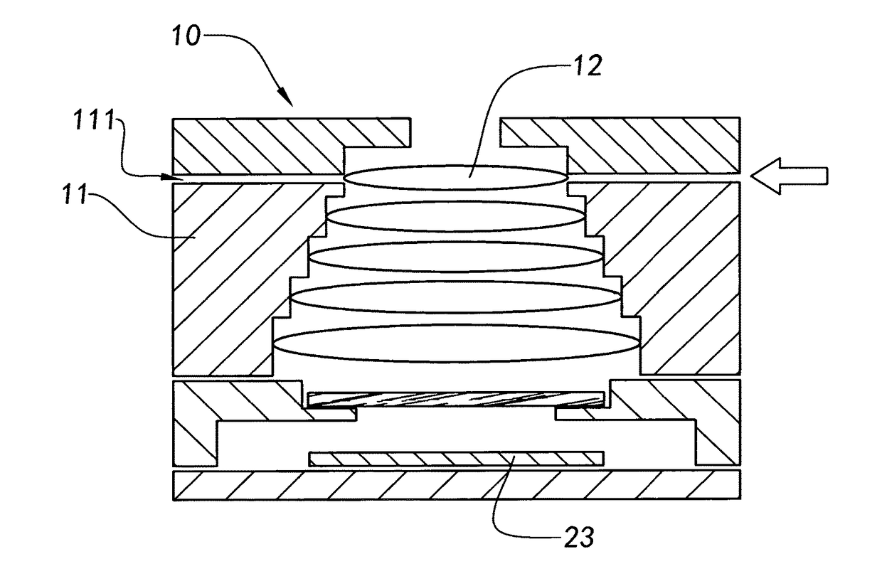
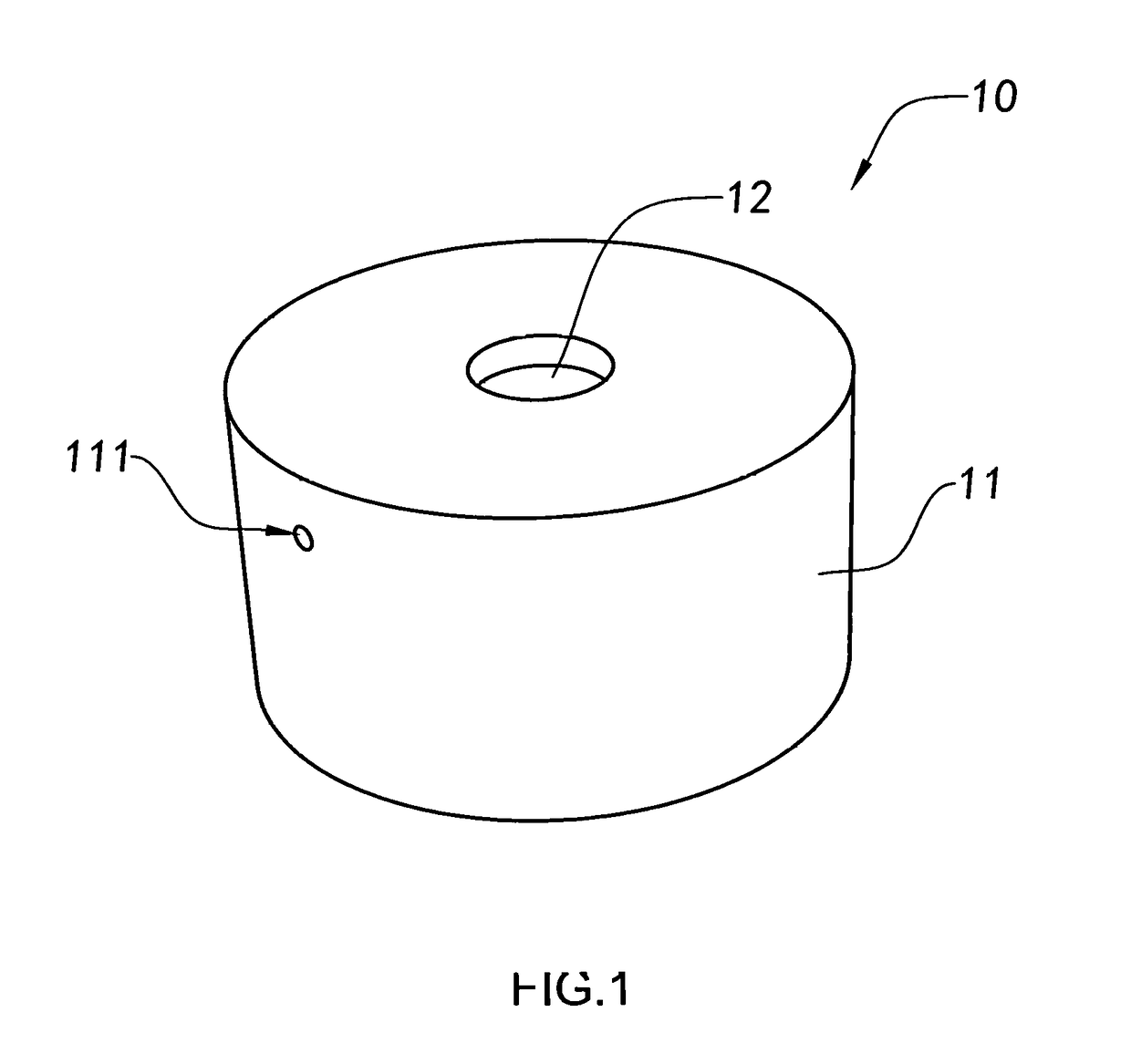
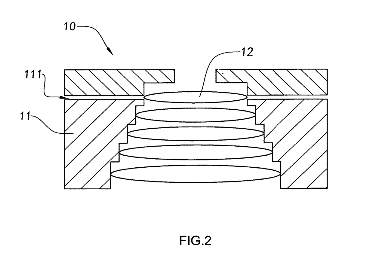
[0113]Referring to FIG. 1 and FIG. 2 of the drawings, an adjustable optical lens 10 according to a preferred embodiment of the present invention is illustrated. A central axis line of the adjustable optical lens 10 is able to be adjusted again after the adjustable optical lens 10 has been produced, so that when the adjustable optical lens 10 is subsequently applied to an imaging system, the central axis line of the adjustable optical lens 10 can be adjusted based on specific parameters of the ima...


PUM

PropertyMeasurementUnit
sizeaaaaaaaaaa
photosensitiveaaaaaaaaaa
space distanceaaaaaaaaaa

Abstract

An adjustable optical lens and camera module and manufacturing method thereof are provided, wherein the camera module includes an optical sensor and an adjustable optical lens. The adjustable optical lens, which is arranged in a photosensitive path of the optical sensor, includes an optical structural member and at least two lenses. Each of the lens is arranged in an internal space of the optical structural member along an axial direction of the optical structural member, wherein before packaging the adjustable optical lens and the optical sensor, at least one position of the lens in the internal space of the optical structural member is able to be adjusted, so that a central axis line of the adjustable optical lens and a central axis line of the optical sensor are coincided, so as to improve the image quality of the camera module.

Description

NOTICE OF COPYRIGHT[0001]A portion of the disclosure of this patent document contains material which is subject to copyright protection. The copyright owner has no objection to any reproduction by anyone of the patent disclosure, as it appears in the United States Patent and Trademark Office patent files or records, but otherwise reserves all copyright rights whatsoever.BACKGROUND OF THE PRESENT INVENTION[0002]Field of Invention[0003]The present invention relates to an optical equipment, and more particularly to an adjustable optical lens and camera module and the manufacturing method thereof.[0004]Description of Related Arts[0005]As mobile electronic devices have become popular, a camera module related technologies applied to mobile electronic devices for images capturing (e.g. videos or pictures) for the user have been rapidly developed and improved. Meanwhile, the camera module has recently and widely applied to various fields, including health care, safety and security, and indu...

Claims


Application Information

Patent Timeline
Patent Type & Authority Applications(United States)
IPC IPC(8): G02B7/00G02B7/02H04N5/225G02B7/09
CPCG02B7/003G02B7/09H04N5/2254G02B7/025G02B7/006G02B7/021G02B7/00G02B7/023H01L27/14618H04N23/55H04N23/54H04N23/57G03B9/02G03B17/12B29C65/7802
Inventor WANG, MINGZHUZHAO, BOJIEDING, LIANGLIU, CHUNMEICHEN, FEIFANGUO, NANJIANG, HENG
Owner NINGBO SUNNY OPOTECH CO LTD
Why Eureka
Try Eureka