Electricity storage system

a technology of electric storage system and capacitor unit, which is applied in the directions of transportation and packaging, emergency protective circuit arrangement, and battery arrangement for several simultaneous batteries, etc., can solve the problems of leakage current flowing to the diode, the voltage value to be applied to the activated current breaker cannot be decreased, etc., to achieve the effect of suppressing an excessive increase in the voltage value of the capacitor uni

Inactive Publication Date: 2017-05-04
TOYOTA JIDOSHA KK
View PDF5 Cites 12 Cited by
  • Summary
  • Abstract
  • Description
  • Claims
  • Application Information

AI Technical Summary

Benefits of technology

[0006]For example, if the current breaker of a single battery included in the first battery group is activated, the voltage value of the first battery group is applied to the activated current breaker. In a configuration in which the intermediate line is omitted, when the current breaker is activated, the voltage value of the assembled battery is applied to the activated current breaker. In this way, in the configuration in which the intermediate line is provided, it is possible to decrease the voltage value to be applied to the activated current breaker compared to the configuration in which the intermediate line is omitted.
[0016]Each diode is connected in parallel to each electricity storage group through the first intermediate line. Accordingly, each capacitor is connected in parallel to each electricity storage group through the second intermediate line and the first intermediate line. In a configuration in which the second intermediate line is not provided, if the current breaker is activated at the time of charging of the electricity storage device, a charge current flows only to the capacitor unit, and the voltage value of the capacitor unit easily increases. Here, if the second intermediate line is provided, the charge current can also be made to flow to the electricity storage group not including the activated current breaker. In this way, the charge current is distributed to the electricity storage group and the capacitor connected in parallel, whereby it is possible to suppress an increase in the voltage value of the capacitor. As a result, it is possible to suppress an increase in the voltage value of the capacitor unit having a plurality of capacitors.
[0020]The relays are provided as described above, whereby it is possible to break the current path in which the electricity storage group and the diode are connected in parallel. When a failure (short-circuiting or leakage) in the diode occurs, if the electricity storage group and the diode are kept connected in parallel, the discharge current of the electricity storage group flows from the cathode toward the anode in the diode, and the electricity storage group is continuously discharged. Here, if the relay provided on the current path in which the discharge current of the electricity storage group flows is switched off, it is possible to prevent the electricity storage group from being continuously discharged.
[0034]When charging the electricity storage device, if the current breaker is activated, the capacitor unit is charged. Here, the Zener diode is connected in parallel to the capacitor unit. Accordingly, the voltage value of the capacitor unit is not greater than the breakdown voltage value of the Zener diode. With this, it is possible to suppress an excessive increase in the voltage value of the capacitor unit. For example, the more the voltage value of the capacitor unit increases, the more the voltage value to be applied to the activated current breaker may increase. In this case, an increase in the voltage value of the capacitor unit is suppressed, thereby suppressing an increase in the voltage value to be applied to the activated current breaker.

Problems solved by technology

Accordingly, in Japanese Patent No. 05333671, if the current breaker is activated when the power of the assembled battery is supplied to the load, it is not possible to decrease the voltage value to be applied to the activated current breaker.
Here, when the diode has a failure, a leakage current may flow to the diode.

Method used


Image

  • Electricity storage system
  • Electricity storage system
  • Electricity storage system

Examples


Embodiment Construction

[0057]Hereinafter, embodiments will be described.

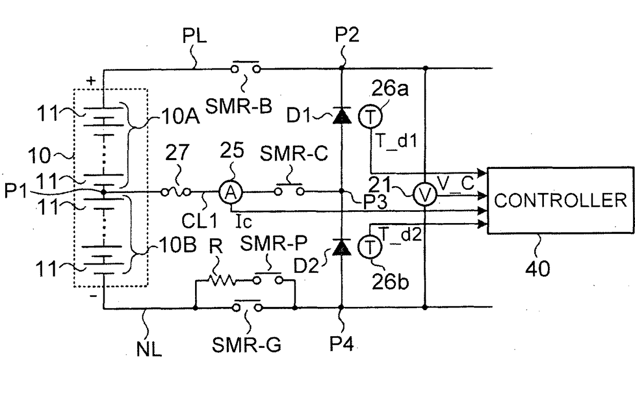
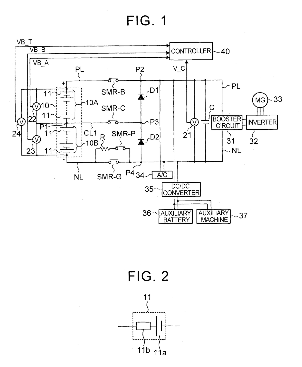
[0058]A battery system (corresponding to an electricity storage system of some embodiments) according to Example 1 will be described. FIG. 1 is a schematic view showing the configuration of the battery system. The battery system shown in FIG. 1 is mounted in a vehicle.

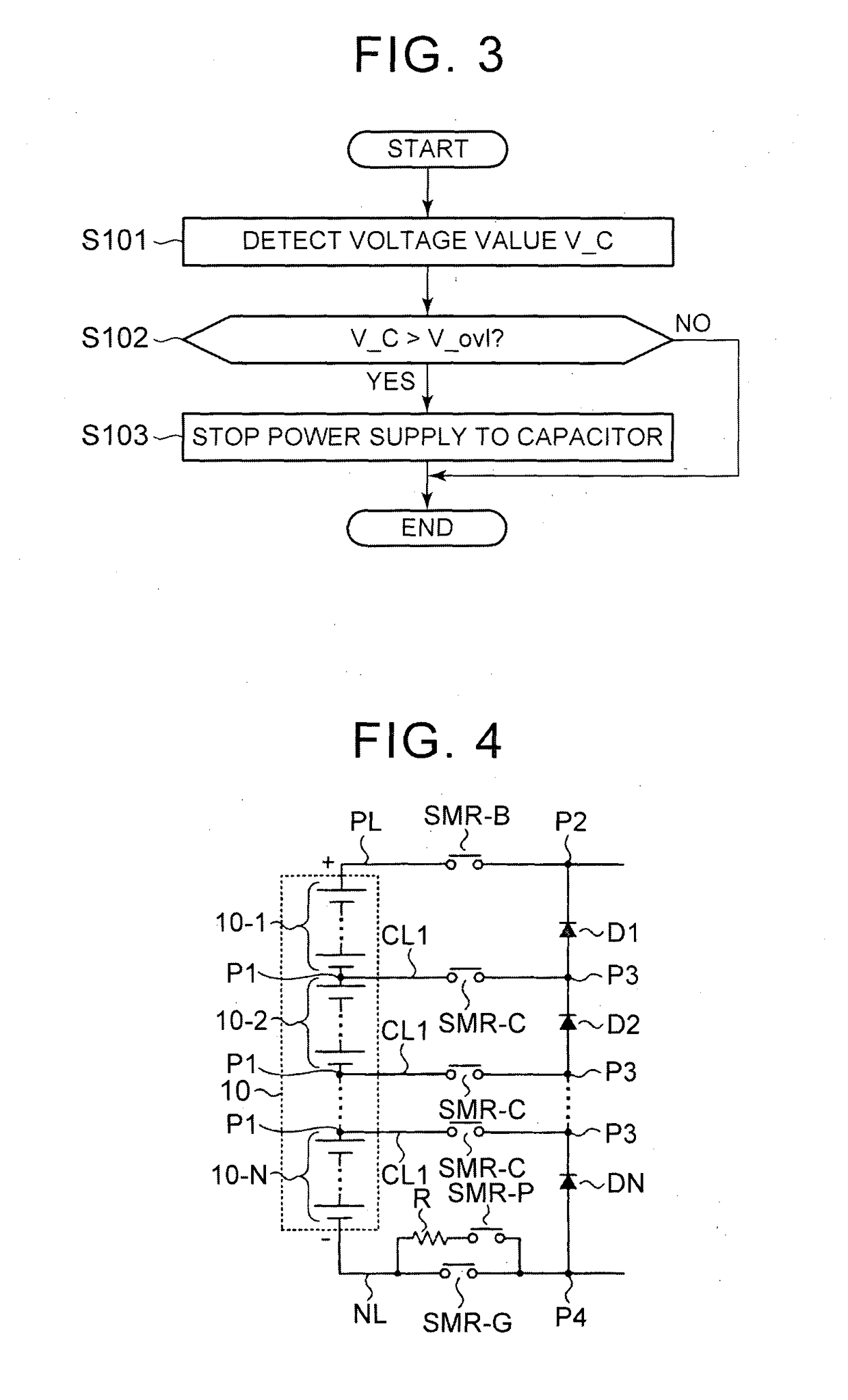
[0059]An assembled battery (corresponding to an electricity storage device of some embodiments) 10 has a plurality of single batteries (corresponding to electricity storage elements of some embodiments) 11 connected in series. As the single batteries 11, secondary batteries are used. Instead of secondary batteries, electric double layer capacitors (corresponding to electricity storage elements of some embodiments) can be used. The assembled battery 10 is divided into two battery groups (corresponding to electricity storage groups of some embodiments) 10A, 10B, and the battery groups 10A, 10B are connected in series. Each of the battery groups 10A, 10B has a plurality of ...


PUM


Abstract

An electricity storage system includes an electricity storage device, a positive electrode line, a negative electrode line, a capacitor, at least two diodes, and a first intermediate line. The electricity storage device is able to supply power to a load. The electricity storage device includes at least two electricity storage groups connected in series. The electricity storage group includes at least two electricity storage elements connected in series. Each electricity storage element includes a current breaker. The capacitor is connected to the positive and negative electrode lines. At least two diodes are connected in series between the positive electrode line and the negative electrode line and are respectively connected in parallel to the electricity storage groups. The first intermediate line is connected between a first connection point at which the electricity storage groups are connected together and a second connection point at which the diodes are connected together.

Description

CROSS-REFERENCE TO RELATED APPLICATIONS[0001]This application is a National Stage of International Application No. PCT / IB2015 / 000772 filed on May 28, 2015, which claims priority to Japanese Patent Application No. 2014-113598, filed May 30, 2014, the entire contents of which are hereby incorporated by reference.BACKGROUND[0002]1. Field[0003]The present disclosure relates to an electricity storage system which has an electricity storage device with a plurality of electricity storage elements connected in series, each electricity storage element including a current breaker.[0004]2. Description of Related Art[0005]In Japanese Patent No. 05333671, an intermediate line is provided in addition to a positive electrode line and a negative electrode line, whereby capacitors are respectively connected in parallel to two battery groups (first battery group and second battery group) connected in series. When the power of an assembled battery constituted by the two battery groups is not supplied ...

Claims


Application Information

Patent Timeline
Patent Type & Authority Applications(United States)
IPC IPC(8): H02H1/00H02J7/00H02H3/087H02J7/34
CPCH02H1/0007H02H3/087H02J7/0063H02J7/345H02J7/0016H02J7/0013H02J7/00712H02J2310/48Y02T10/70
Inventor NISHI, YUJITANABE, YUKINARITANAKA, HIROMASAKAIYA, HIROYUKIHIRASAWA, TAKAHIKOIZUMI, JUNTA
Owner TOYOTA JIDOSHA KK
Why Eureka
Try Eureka