
Enclosure for modular construction systems

a modular construction and enclosure technology, applied in the field of construction, can solve the problems of limiting work, high time consumption of operators, and consequently more expensive labor costs

Inactive Publication Date: 2017-05-11
SUSTAINABLE ENERGY&HOUSING SL
View PDF16 Cites 8 Cited by
  • Summary
  • Abstract
  • Description
  • Claims
  • Application Information

AI Technical Summary

Benefits of technology

The present invention provides an enclosure for modular systems that has several technical effects. Firstly, it allows for a simpler and faster solution compared to current techniques. Secondly, it prevents the need for welding and plastering the heads of connecting elements, which saves time. Thirdly, it increases resistance to extreme wind conditions, ensuring the integrity of the panels without any deterioration. Fourthly, it includes supporting metal bars that are located in an intermediate position between the columns of panels, which further strengthens the enclosure against stress and forces of extreme wind. Fifthly, it allows for easy and minimal time consumption for connecting and coupling the panels, while ensuring structural rigidity and no joins between different levels or floors of the modular construction system. Lastly, it allows for configuring all kinds of façade finished surfaces, including ventilated façades, with the same materials as traditional construction systems.

Problems solved by technology

However, years of experience in the field of modular construction has resulted in the detection of various problems and inconveniences that have not yet been given a truly effective and reliable solution.
A list of some of these problems follows below:Current systems require performing “welds” between the main steel structure and the different pieces or battens, to which the enclosures are then screwed.The above point of screwing of the enclosures to the battens required a later stage of “plastering” the heads of the connecting elements for an optimal aesthetic finish.These phases of welding and plastering each of the heads of the connecting elements pose high time consumption for the operators, with consequent more expensive labour costs.In addition, current systems significantly limit the work of architectural firms, mainly due to the low resistance of their modules as they are not self-supporting, to the limitation of their dimensions and to the limitation of their façade finishes.

Method used


Image

  • Enclosure for modular construction systems
  • Enclosure for modular construction systems
  • Enclosure for modular construction systems

Examples


Embodiment Construction

[0031]An example of a preferred embodiment of the invention is described below with reference to the above-cited figures, without limiting or reducing the scope of protection of the present invention.

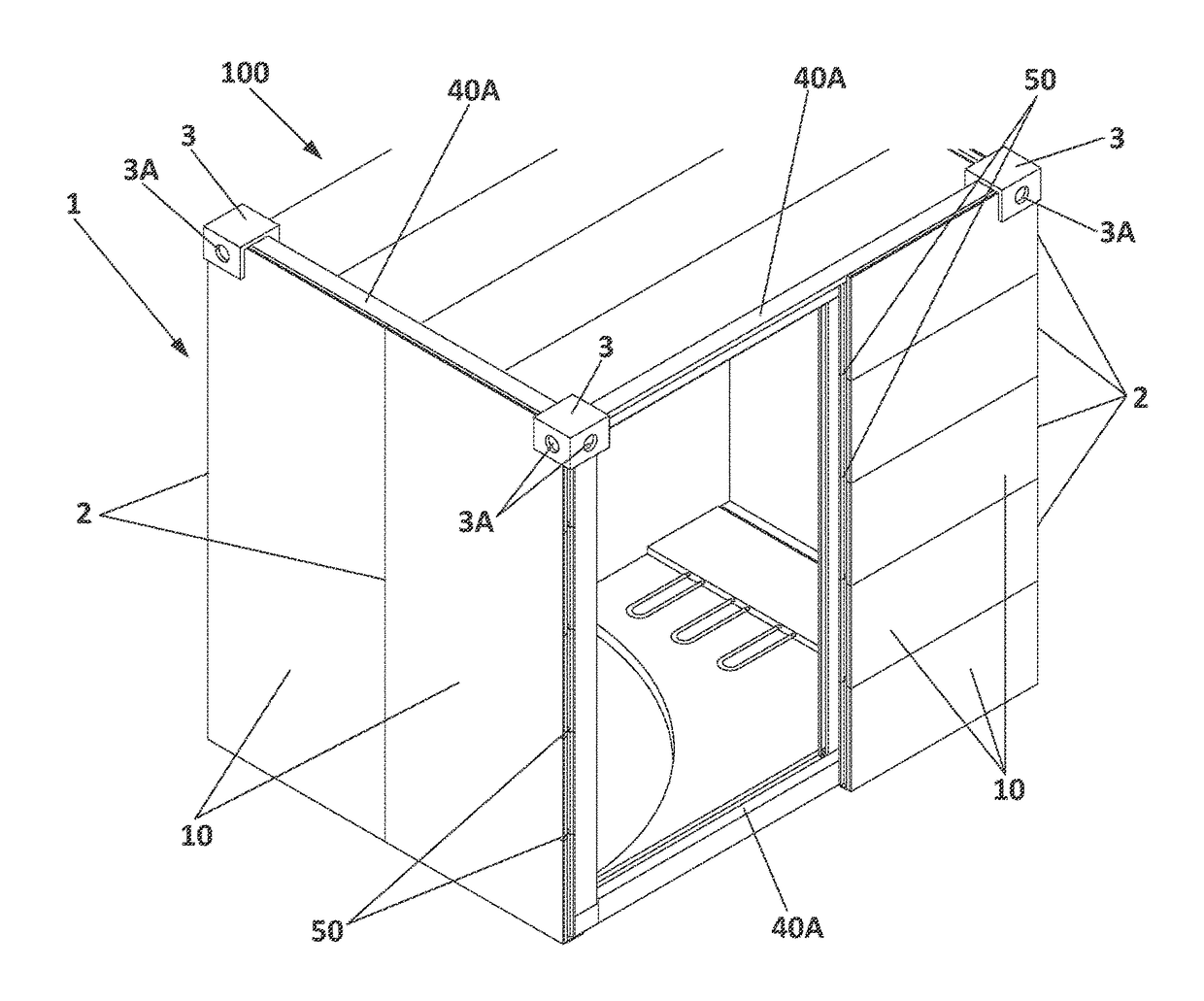
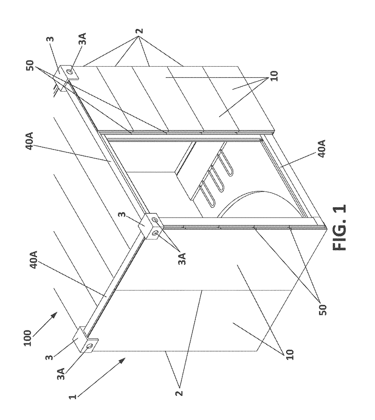
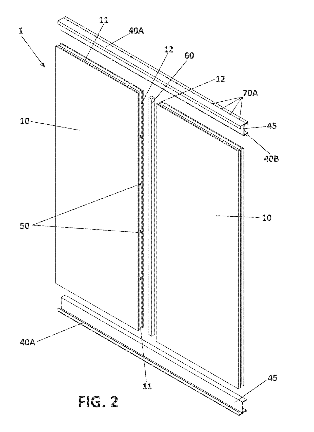
[0032]A modular construction (100) made up by the enclosure (1) of the invention, and which comprises a plurality of panels (2) having a tongue and groove joint (50) at their upper, bottom and side edges, as shown in FIGS. 1 and 2, for coupling together to form a vertical column of panels (2), as depicted in FIG. 1, can be seen in FIG. 1.

[0033]More specifically, each of said panels (2) are formed in turn by a multilayer outer piece (10), a multilayer inner piece (20), and an intermediate air chamber (30) arranged between the outer and inner pieces (10, 20), as reflected in FIGS. 3 and 4. At this point, FIGS. 5, 6A and 6B should be mentioned where, in addition to the various components and inner pieces of the panels (2) cited above, a top view of the connection between two panels (2) can...


PUM


Abstract

A simple and fast solution over the current modular construction techniques does not require welding or having to plaster the heads of the connecting elements, while allowing the increase and reinforcement of their resistance to the wind in locations with exposure to extreme winds. An enclosure includes a number of panels formed by at least one multilayer outer piece, a multilayer inner piece, and an intermediate air chamber, wherein the outer pieces of each panel have transverse grooves and recesses located at the side edges thereof. The enclosure includes bracing metal bars coupled to the groove of the outer pieces. The enclosure further includes supporting metal bars coupled vertically in correspondence with the recesses of the outer pieces.

Description

BACKGROUND OF THE INVENTION[0001]Field of the Invention[0002]The present invention pertains to the field of construction, and more particularly to industrialised modular construction systems for buildings.[0003]The object of the present invention is an enclosure for industrialised modular construction systems that, besides being a simple and fast solution compared to current techniques, without the need for welding or having to plaster the heads of connecting elements, allows, at the same time, compliance with the wind resistance regulations.[0004]Description of Related Art[0005]Currently, industrialised modular construction has become well known and widespread, where from modules or standardised sections, buildings of all types are manufactured in advance far from their destination, usually in a workshop, factory or warehouse, to be moved afterwards to their final location for positioning and final assembly.[0006]Nowadays, there is a great amount of scientific literature on the man...

Claims


Application Information

Patent Timeline
IPC IPC(8): E04H1/00E04H5/02
CPCE04H5/02E04H1/005E04B1/3483E04B2/42E04B2/58E04C2/38E04H2001/1283
Inventor REBOLLAR BULDAIN, PEDRO
Owner SUSTAINABLE ENERGY&HOUSING SL
Learn More