Turbine component having a seal slot and additive manufacturing process for making same

a technology of additive manufacturing and turbine components, applied in the field of seals, can solve the problems of high variability, leakage through pathways, inefficiency of aircraft engines, etc., and achieve the effect of reducing the size of the opening

Active Publication Date: 2017-05-11
GENERAL ELECTRIC CO
View PDF5 Cites 12 Cited by
  • Summary
  • Abstract
  • Description
  • Claims
  • Application Information

AI Technical Summary

Benefits of technology

[0008]According to one aspect of the present invention, there is provided a method of forming a sealing structure in a turbine component that has a seal slot. The seal slot includes walls that define an opening therebetween. The method includes using an additive manufacturing process to form a neck structure on at least one of the walls so as to reduce a size of the opening.
[0009]According to another aspect of the present invention, there is provided a method of forming a sealing structure in a turbine component having a seal slot sequentially with a spline seal. The slot includes walls that define an opening therebetween and at least a portion of the spline seal positioned in the opening. The method includes using an additive manufacturing process to form a neck structure on at least one of the walls so as to reduce a size of the opening and to form a spline seal positioned within the opening.

Problems solved by technology

It is known that leakage at the gap between adjacent segments leads to inefficiencies in aircraft engines.
One problem with conventional spline slots and splines is that leakage occurs through pathways defined between the substantially parallel spline and adjacent wall of the spline slot.
Another problem with conventional spline slots and methods for forming them is that the ability to leave a blind access region behind additional features cannot be accommodated by casting, and would require extreme measures to machine thereby leading to highly variable results.
Another problem with conventional spline slots and spline configurations is that the spline can be removed from a spline slot inadvertently.

Method used


Image

  • Turbine component having a seal slot and additive manufacturing process for making same
  • Turbine component having a seal slot and additive manufacturing process for making same
  • Turbine component having a seal slot and additive manufacturing process for making same

Examples


Embodiment Construction

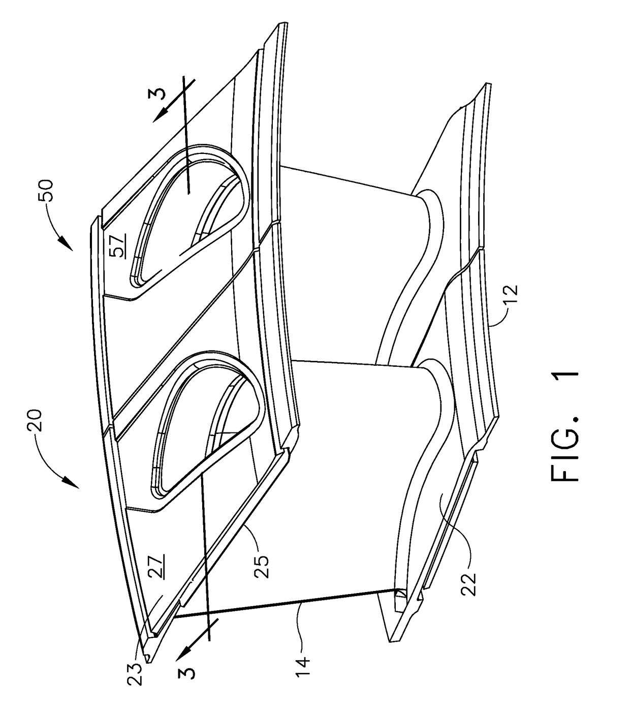
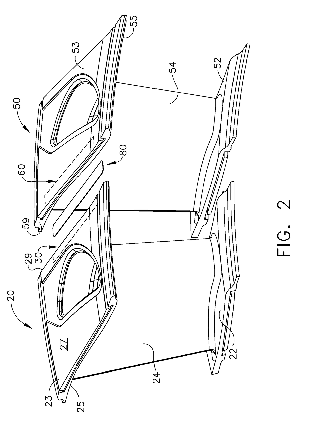
[0029]Referring to the drawings wherein identical reference numerals denote the same elements throughout the various views, FIGS. 1-3 show an exemplary sealing apparatus 10.

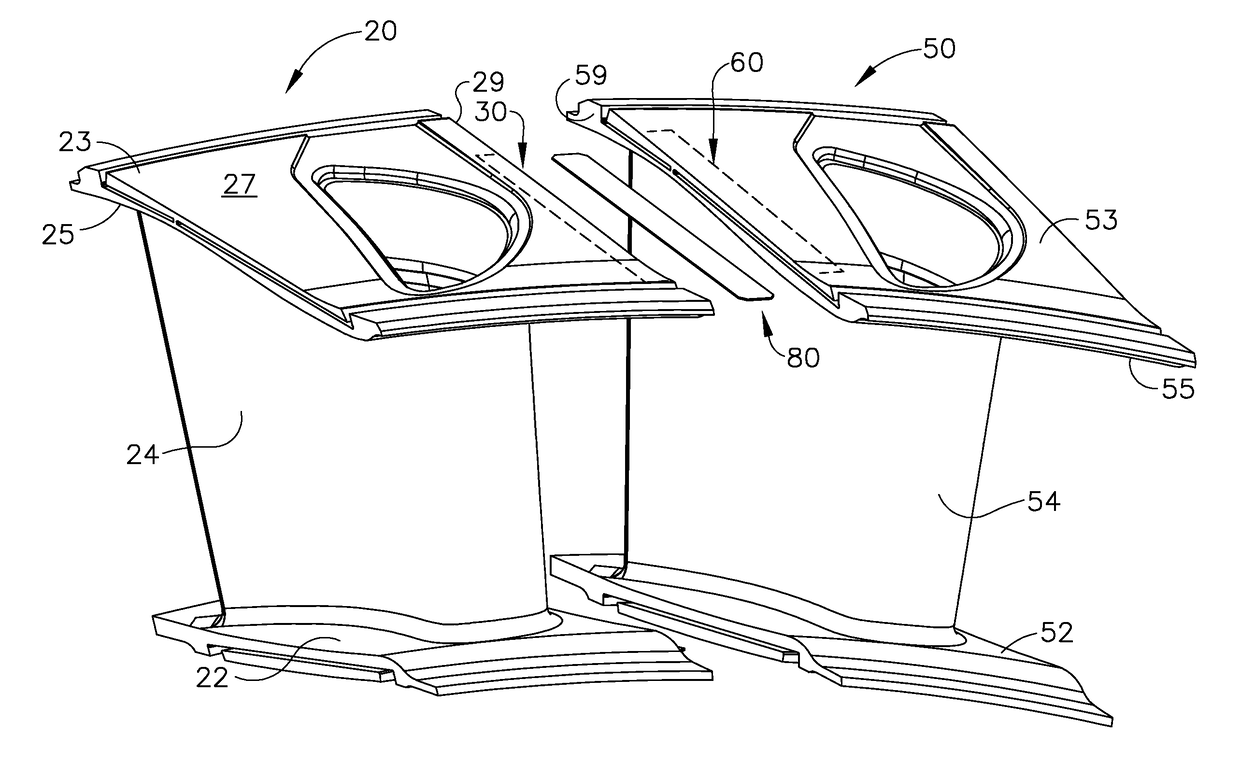
[0030]Sealing apparatus 10 is configured to reduce leakage through a gap between a first nozzle segment 20 and a second nozzle segment 50. It should be noted that the nozzle segment 20 and 50 are used merely as examples. The principles described herein may be applied to any set of turbine components which are assembled with a spline seal therebetween.

[0031]The first nozzle segment 20 includes an inner band 22 that is connected to an outer band 23 by an airfoil 24. The outer band 23 has an inboard surface 25 and an outboard surface 27. An end face 29 of the outer band 23 is positioned between the inboard surface 25 and the outboard surface 27.

[0032]Referring now to FIGS. 1-3, a spline slot 30 is defined in the outer band 23 and extends inward from the end face 29 and is configured to receive a spline seal 80. The ...


PUM

PropertyMeasurementUnit
thicknessaaaaaaaaaa
sizeaaaaaaaaaa
structureaaaaaaaaaa

Abstract

A method of forming a structure in a turbine component having a seal slot, the slot including walls defining an opening therebetween, the method includes the step of using an additive manufacturing process to form a neck structure on a wall so as to reduce a size of the opening.

Description

BACKGROUND OF THE INVENTION[0001]The present invention relates to seals for the reduction of leakage between turbine components and more specifically to seal slots in nozzle segments having complex profiles and an additive manufacturing process for making such seal slots.[0002]Gas turbine engine components such as turbine nozzles are often configured as a ring of side-by-side segments. It is known that leakage at the gap between adjacent segments leads to inefficiencies in aircraft engines. Conventional ways to reduce this leakage include installation of sealing slots and splines positioned such that leakage pathways between the segments are blocked or impeded. In this regard, each segment has an edge having a spline slot formed therein. Adjacent spline slots of two adjacent segments are configured to receive opposite sides of the same spline. In this manner, leakage pathways along the gap between two adjacent segments are reduced by cooperatively engaged splines and spline slots.[0...

Claims


Application Information

Patent Timeline
Patent Type & Authority Applications(United States)
IPC IPC(8): F01D11/00B22F3/105B23K26/342C04B35/64B28B1/00B29C67/00F01D9/04B22F7/02
CPCF01D11/005B29L2031/08B22F3/1055B22F7/02C04B35/64B28B1/001B29C67/0077B23K26/342F05D2220/32F05D2230/30F05D2240/128F05D2240/55F05D2300/17B33Y10/00B33Y80/00F01D9/041C23C24/103C23C24/106F01D5/288F01D9/02F01D11/00B22F10/28B22F5/009B22F5/04B22F7/08B29C64/153F05D2260/36B22F2999/00Y02P10/25B22F2005/005Y02T50/60
Inventor BUNKER, RONALD SCOTTCORREIA, VICTOR HUGO SILVA
Owner GENERAL ELECTRIC CO
Why Eureka
Try Eureka