
Automatic control method for zone controller

a control method and automatic technology, applied in the field of zone controllers, can solve the problems of not being able to the mode and the mode switch conditions may not satisfy users, and the zc judgment made in the operation may not meet the demands of users, so as to achieve the effect of more useful to users

Inactive Publication Date: 2017-05-11
DELTA ELECTRONICS INC
View PDF6 Cites 0 Cited by
  • Summary
  • Abstract
  • Description
  • Claims
  • Application Information

AI Technical Summary

Benefits of technology

The present invention provides a method for a self-configurable computer system that allows users to set up multiple events, trigger conditions of each event, multiple operation modes, and mode switch conditions of switching among each operation mode all by themselves. This results in a more diversified operation modes that meet the user's true demands. Additionally, the system automatically controls according to the self-configured operation modes, making it more useful to users.

Problems solved by technology

Though, the above mentioned modes were pre-defined when a ZC is in a factory, users are not allowed to make any changes.
Accordingly, the judgment a ZC made in operations may not meet the demands of the users.
In other words, the modes and the mode switch conditions may not satisfy the users.
However, some users have the habit to leave one light on when leaving a room, there is no one staying in the room.
Under such circumstance, the automatic mode switching of the ZC does not meet user demands.
Further, in related prior art, the controls performed by ZC under each mode are also predetermined and users are not allowed to change.
nder the circumstance, if the users preferred hotter or cooler environment, the above controls under the full automation mode of the ZC may not meet user demands.

Method used


Image

  • Automatic control method for zone controller
  • Automatic control method for zone controller
  • Automatic control method for zone controller

Examples


second embodiment

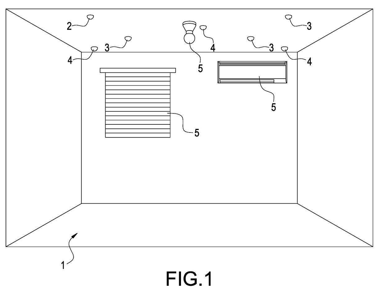
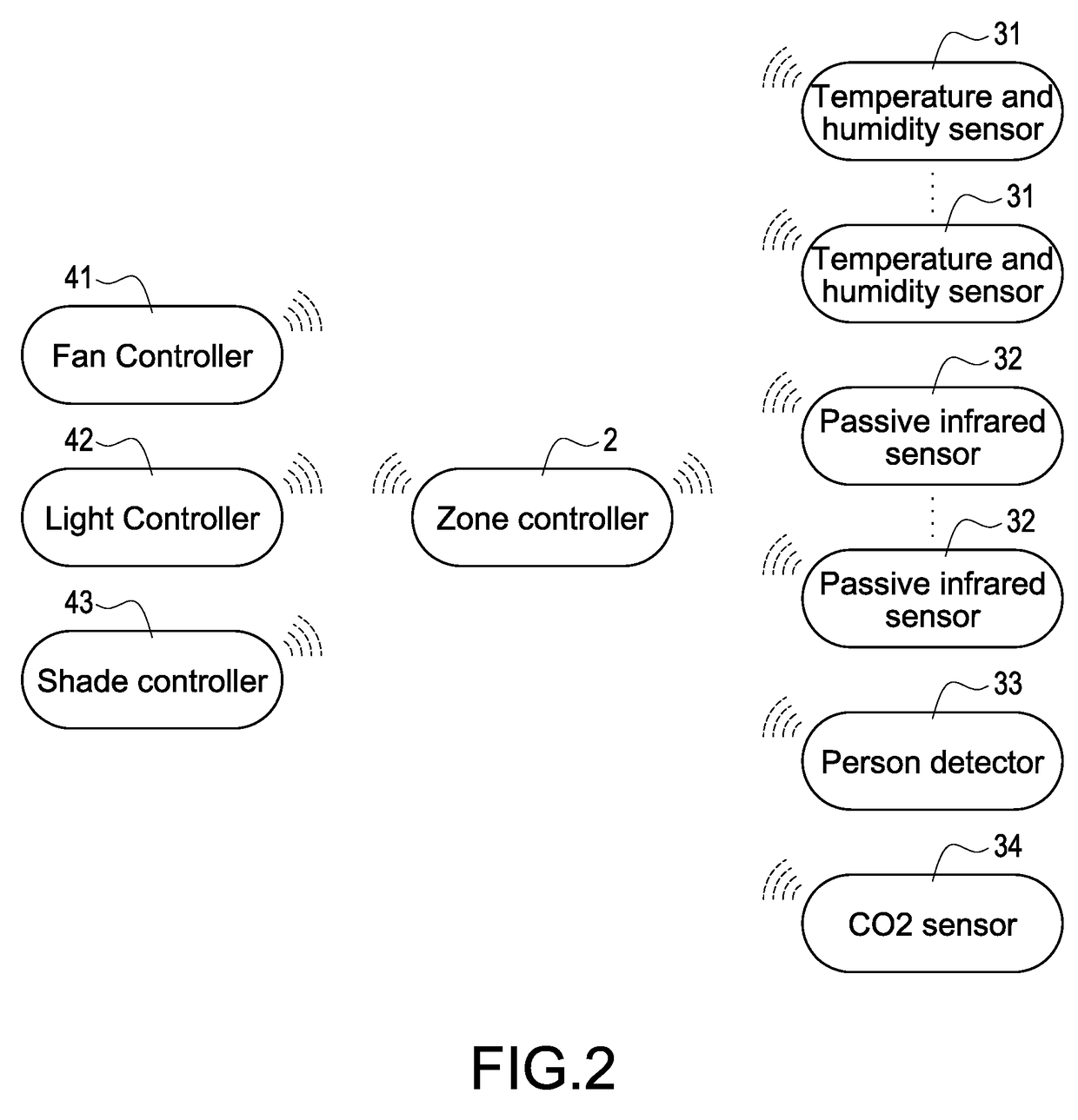
[0025]Refer to FIG. 1 and FIG. 2, FIG. 1 and FIG. 2 are respectively control system schematic diagrams of the first and the second embodiment according to the present invention. The present invention discloses an automatic control method for a zone controller, which is used for a zone controller (ZC) 2 disposed in an indoor space 1 (for example living room, bed room, meeting room or offices, etc.). In the embodiment, a plurality of sensors 3, a plurality of apparatus controllers 4 and a plurality of indoor apparatuses 5 are further disposed in the indoor space 1. The ZC 2 is respectively connected to the plurality of sensors 3 and the plurality of apparatus controllers 4 wired or wirelessly, the plurality of apparatus controllers 4 is connected with the plurality of indoor apparatuses 5 and controls the indoor apparatuses 5 respectively.

[0026]The plurality of sensors 3 are used for sensing the environment status in the indoor space 1. In the embodiment, the plurality of sensors 3 co...

third embodiment

[0031]FIG. 3 is a control system schematic diagram of the third embodiment according to the present invention. In the embodiment, the ZC 2 is disposed in the indoor space 1 of a building (not shown in diagram). In particular, the building has a plurality of the indoor space 1, and a control system set consisting of the ZC 2, the plurality of sensors 3, the plurality of apparatus controllers 4 and the plurality of indoor apparatuses 5 respectively disposed in each indoor space 1. Thus, the environment comfort level in the plurality of indoor spaces 1 is respectively controlled and improved via the plurality of control system sets.

[0032]As shown in FIG. 3, the building has a central server 6. The central server 6 connects to the plurality of ZCs 2 disposed in the building via a network system. The central server 6 collects the environment status in each indoor space 1. In an embodiment, an administrator of the building performs a control operation via the central server 6. Each ZC 2 d...

first embodiment

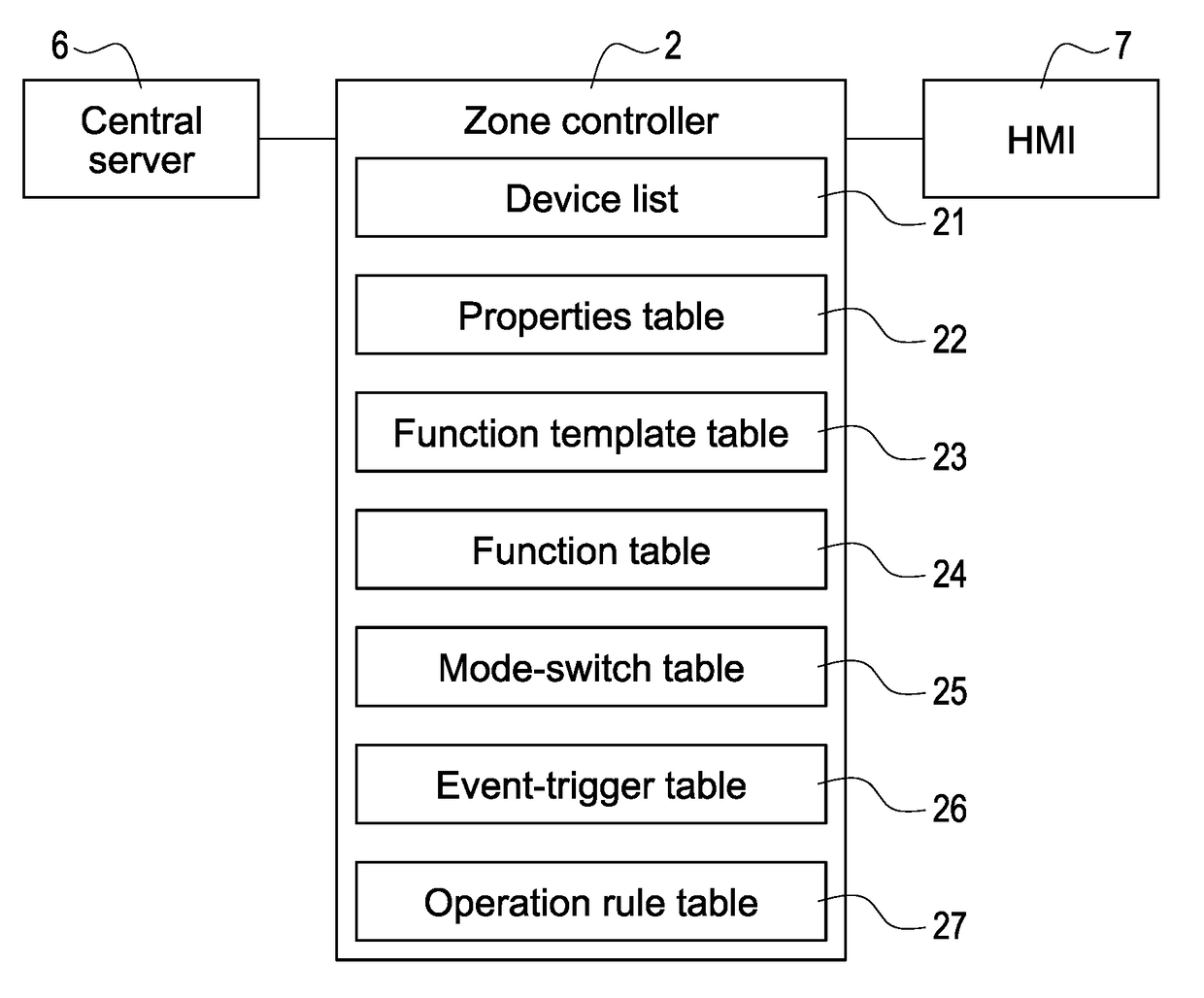
[0033]FIG. 4 is a zone controller block diagram of the first embodiment according to the present invention. As shown in the diagram, the ZC 2 in the embodiment connects to a Human Machine Interface (HMI) 7 via a wired or wireless connection, accepts the instruction sent by the HMI 7, and sends the data such as the sense data of the plurality of sensors 3 and the current using operation mode to the HMI 7 to store or display thereto. Therefore, a user can operate the ZC 2 and receives related information of the indoor space 1 via the HMI 7. The HMI 7 for example is a keyboard, mouse, screen set or touch control screen, or web interface wirelessly connected to the ZC 2, and the scope is not limited thereto.

[0034]In the embodiment, the users perform a set up operation via the HMI 7. The ZC 2 determines if the ZC 2 needs to switch mode according to the sense data from the plurality of sensors 3 and the logic operation result of the set up operation of the HMI 7. It should be noted that, ...


PUM


Abstract

An automatic control method for zone controller adopted by a zone controller connected to multiple sensors and multiple apparatus controllers in an indoor space is disclosed. The zone controller receives sense data of the sensors, and inquires an event-trigger table according to the sense data for determining if the current environment matches with a trigger condition of any predetermined event. When any event is triggered, the zone controller inquires a mode-switch table according to the triggered event for determining if the triggered event matches with any predetermined mode switch condition. When the triggered event matches with any mode switch condition, the zone controller automatically switches to a corresponding operation mode, and performs corresponding operation on the multiple apparatus controllers under the switched operation mode.

Description

BACKGROUND OF THE INVENTION[0001]Field of the Invention[0002]The present invention is related to a zone controller, in particular relates to an automatic control method for zone controller.[0003]Description of Prior Art[0004]In order to perform intelligent controls of a zone (for example a room, a meeting room or an office, etc.), the zone must have at least one zone controller (ZC) and multiple wireless nodes installed (for example, the wireless nodes can be the apparatus controllers for controlling indoor apparatus, or the sensors for sensing indoor and outdoor environment parameters). These sensors collects related data in the zone and provides the data to the ZC, whereby the ZC performs mode switch according to the data, and further performs corresponding controls over the apparatus controllers under different modes.[0005]In general, a ZC works under several modes in related prior art, for example standby mode, full automation mode, semi-automation mode, etc. With the automatic ...

Claims


Application Information

Patent Timeline
Patent Type & Authority Applications(United States)
IPC IPC(8): F24F11/00G05B11/01F24F3/044
CPCF24F11/006F24F3/044F24F11/0012F24F11/0034G05B11/01F24F2011/0068F24F2011/0049F24F2011/0057F24F2011/0063F24F2011/0067F24F2011/0046G05B19/0421F24F11/64G05B15/02G05B2219/2642F24F11/30F24F2110/10F24F2120/10F24F2120/20F24F11/62F24F11/66F24F11/54F24F11/56F24F11/52
Inventor LO, TIEN-SZUCHEN, MENG-SENG
Owner DELTA ELECTRONICS INC
Learn More