Supercharge Your Innovation With Domain-Expert AI Agents!

Passive Infrared Sensor Self Test With Known Heat Source

Active Publication Date: 2017-05-11
GOOGLE LLC
View PDF4 Cites 7 Cited by
  • Summary
  • Abstract
  • Description
  • Claims
  • Application Information

AI Technical Summary

Benefits of technology

The disclosure relates to a device that can detect if a component (e.g. a camera) is not working properly by analyzing infrared radiation. If there is a significant difference in the characteristic of the infrared radiation compared to a test characteristic, the device will determine that the component is not functioning correctly. This technology can be used in various applications such as detecting improper mounting of a device or ensuring proper functionality of components.

Problems solved by technology

The voltage drop between the terminal pins is measured, and if the voltage drop differs from a tolerance value, the sensor is determined to be operating improperly.
A significant drawback of such techniques is that they only evaluate the drive circuitry or amplification circuitry of the sensor device.
Thus in some circumstances, conventional techniques will not detect certain defects in passive infrared sensors.

Method used


Image

  • Passive Infrared Sensor Self Test With Known Heat Source
  • Passive Infrared Sensor Self Test With Known Heat Source
  • Passive Infrared Sensor Self Test With Known Heat Source

Examples


Embodiment Construction

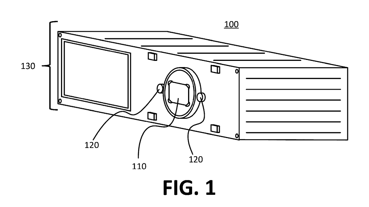
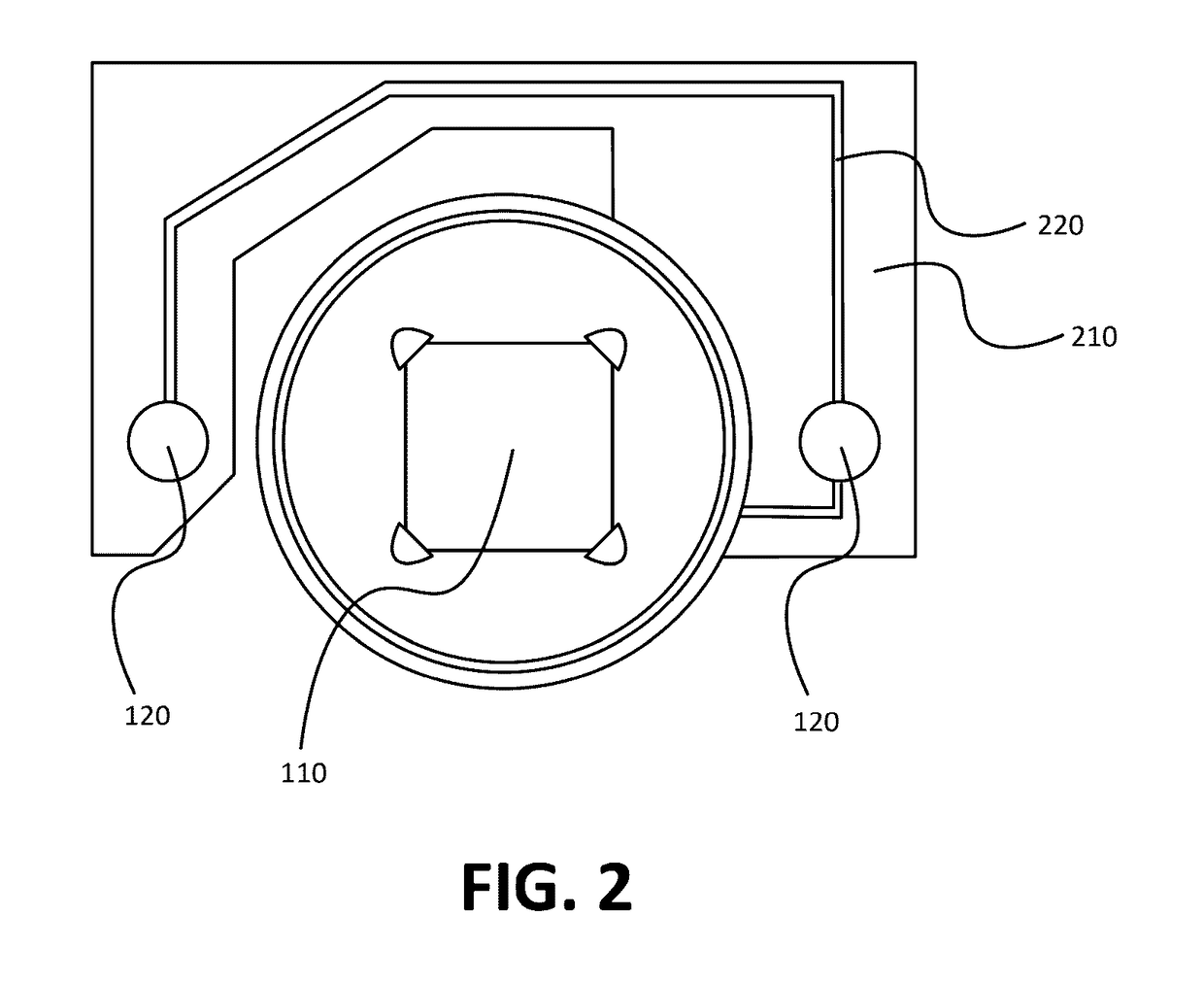
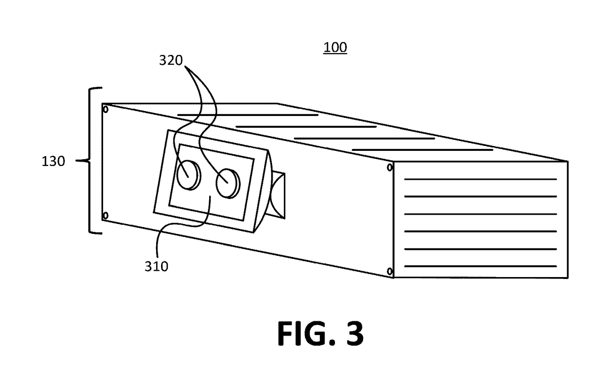
[0022]To address the issues previously described, devices, systems, and techniques as disclosed herein may provide for the self testing of a passive infrared (PIR) sensor using a known heat source emitted from an emission component housed in the same device as the PIR sensor. For example a PIR sensor having a radiation capture component, may be housed within a sensor device. The device may also house radiation emission components, such as light emitting diodes (LEDs), in proximity to the capture component of the PIR sensor. Electronic circuitry within the device may generate a signal that causes the LEDs to emit radiation that includes wavelengths in the infrared spectrum. It may be known that under normal operation the emitted radiation is captured by the capture component of the PIR sensor, and when captured, the PIR sensor generates an output signal having characteristic features, such as a characteristic voltage peak. These known characteristics may be used as test characteristi...


PUM


Abstract

A passive infrared sensor having a radiation capture component may be housed within a sensor device. The device may also house radiation emission components, such as light emitting diodes, in proximity to the capture component. Electronic circuitry within the device may generate a signal that causes the emission components to emit radiation that includes wavelengths in the infrared spectrum. The infrared radiation may be captured at the capture component. Characteristics of a signal generated by the capture component may be compared to test characteristics. Based on this comparison, it may be determined that the passive infrared sensor is not operating properly.

Description

BACKGROUND[0001]Passive infrared sensors generally contain delicate wire bonds and connecting components that are easily broken. The output from a broken passive infrared sensor configured to detect human motion is often indistinguishable from the output of a functioning passive infrared sensor when no human motion is present. Conventional self testing techniques for passive infrared sensors measure sensor operation indirectly. For example, conventional techniques apply a charge to one of two terminal pins connecting the electronic circuitry of the sensor device to pyroelectric material. The voltage drop between the terminal pins is measured, and if the voltage drop differs from a tolerance value, the sensor is determined to be operating improperly. A significant drawback of such techniques is that they only evaluate the drive circuitry or amplification circuitry of the sensor device. Other critical sensor components, such as the pyroelectric material are not evaluated. Thus in some...

Claims


Application Information

Patent Timeline
IPC IPC(8): G01J5/52G01J5/08G01J5/34
CPCG01J5/522G01J2005/0048G01J5/0896G01J5/34G01J5/026G01J5/53G01J5/80
Inventor WITTY, EVANDAI, ANDREW
Owner GOOGLE LLC
Features
  • R&D
  • Intellectual Property
  • Life Sciences
  • Materials
  • Tech Scout
  • Unparalleled Data Quality
  • Higher Quality Content
  • 60% Fewer Hallucinations
Learn More