Wearable Electronic System

a technology of electronic system and wearable, which is applied in the direction of diagnostic recording/measuring, application, coupling device connection, etc., can solve the problems of unsuitable clothing underwear, cumbersome dangling wire cables, slow attachment procedure, etc., and achieves convenient replacement, simplified correct placement of any required skin electrodes, and higher data rate

Inactive Publication Date: 2009-12-10
BELL JONATHAN ARNOLD
View PDF22 Cites 281 Cited by
  • Summary
  • Abstract
  • Description
  • Claims
  • Application Information

AI Technical Summary

Benefits of technology

[0014]There is also a need for electrodes attached to the skin within the wearable electronic system to be easily replaced after a certain number of hours of use. The proposed design will pioneer a method whereby commercially available off the shelf electrodes may be connected and disconnected directly to the electrical harness of the wearable electronic system using a standard snap-fit connector. Donning and doffing of the wearable electronic system could simplify the correct placement of any required skin electrodes. Because the skin electrodes are integrated into the harness, it is considered that by donning the wearable electronic system in an appropriate manner, the electrodes will automatically be positioned within the correct region of the body.
[0015]There are a number of different protocols available for controlling communications along a serial digital data-bus. One of the most common is termed I2C (sometimes pronounced I squared C) and is an acronym for Inter-IC bus. This protocol was developed by the Royal Dutch Philips Company and has been adopted as an industry standard. It is a two-wire bus structure where one wire is used to communicate data and the other wire is for a synchronous clock signal used to latch data into and out of digital devices. Each digital device placed on the bus has it own address number so that it may be addressed uniquely and this address number is usually set by connecting pull-up or pull-down resistors to the leads of the surface mount device package. I2C has 7-bit and 10-bit addressing schemes that allow for more than 100 individually addressable devices on a single bus. The data rate can be as high as 3.4 Mbits / sec. Due to the approximate 8 feet length of the anticipated data-bus, an additional set of resistors and capacitors may be required to dampen any digital signal echoes that may occur. These resistors and capacitors will be placed wherever an I2C device is required on the data-bus. Universal Serial Bus (USB) is another popular protocol commonly used to connect PCs with external devices such as printers. While USB currently allows for higher data rates, the complexity of the protocol software required to correctly operate the devices strung along the bus is potentially an order of magnitude above that required for I2C. As a consequence of this, it is suggested that I2C will simplify design and increase the likelihood of a successful design but does not exclude USB or other types of communications protocol. The initial design will separate the data-bus into individual pieces that interconnect each individual node. Connections between the data-bus and the sensors / circuits will be made using snap-fit electro-mechanical connectors. In addition to the two electrical traces required for I2C communication, a third and fourth trace are required for electrical power and electrical ground respectively.

Problems solved by technology

Highly accurate ECG measurements can require up to 10 separate wire cables connected to the body making the attachment procedure slow and the dangling wire cables cumbersome.
The design concept of grouping the electronic processing and power supply together typically requires a significantly bulky box to house the electronics making it unsuitable for use underneath an item of clothing.
For NASA astronauts this is further complicated by the use of a Liquid Cooling and Ventilation Garment (LCVG) used to cool the body during extra vehicular activities (EVAs) that is a skin tight garment covering the entire skin area of the legs, arms, and torso.

Method used


Image

  • Wearable Electronic System
  • Wearable Electronic System
  • Wearable Electronic System

Examples


Embodiment Construction

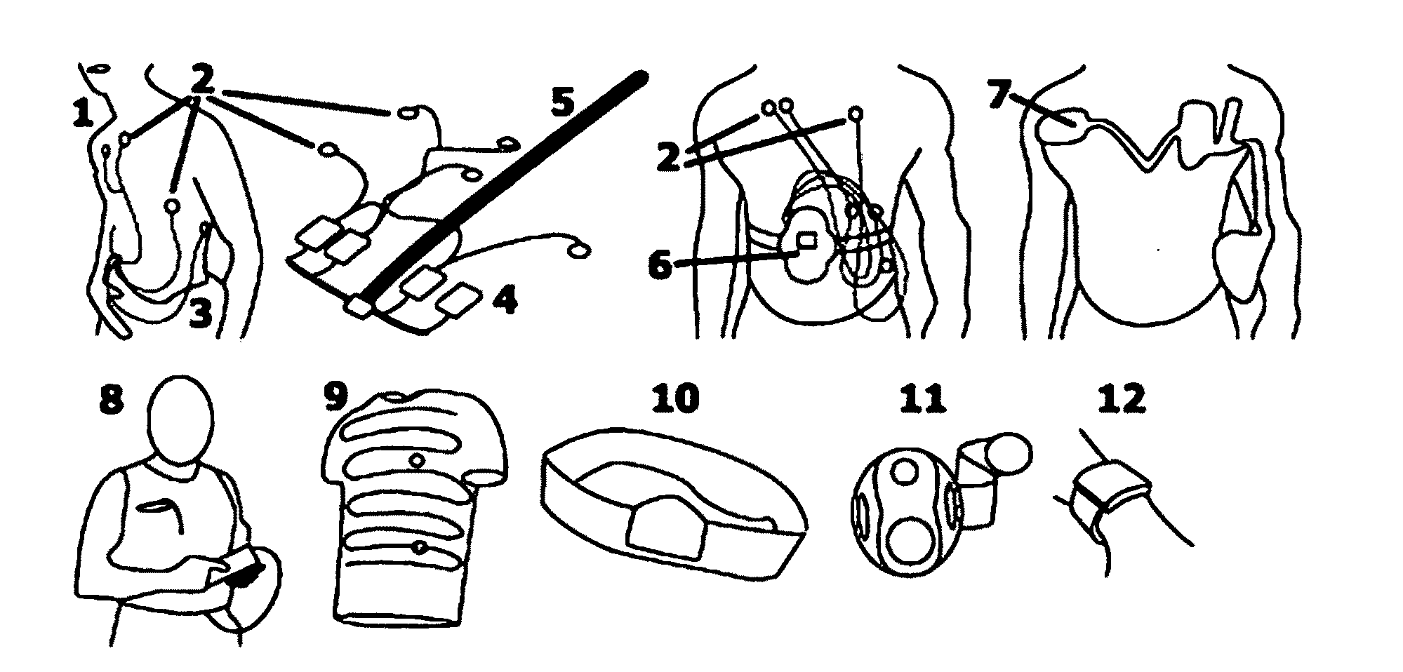
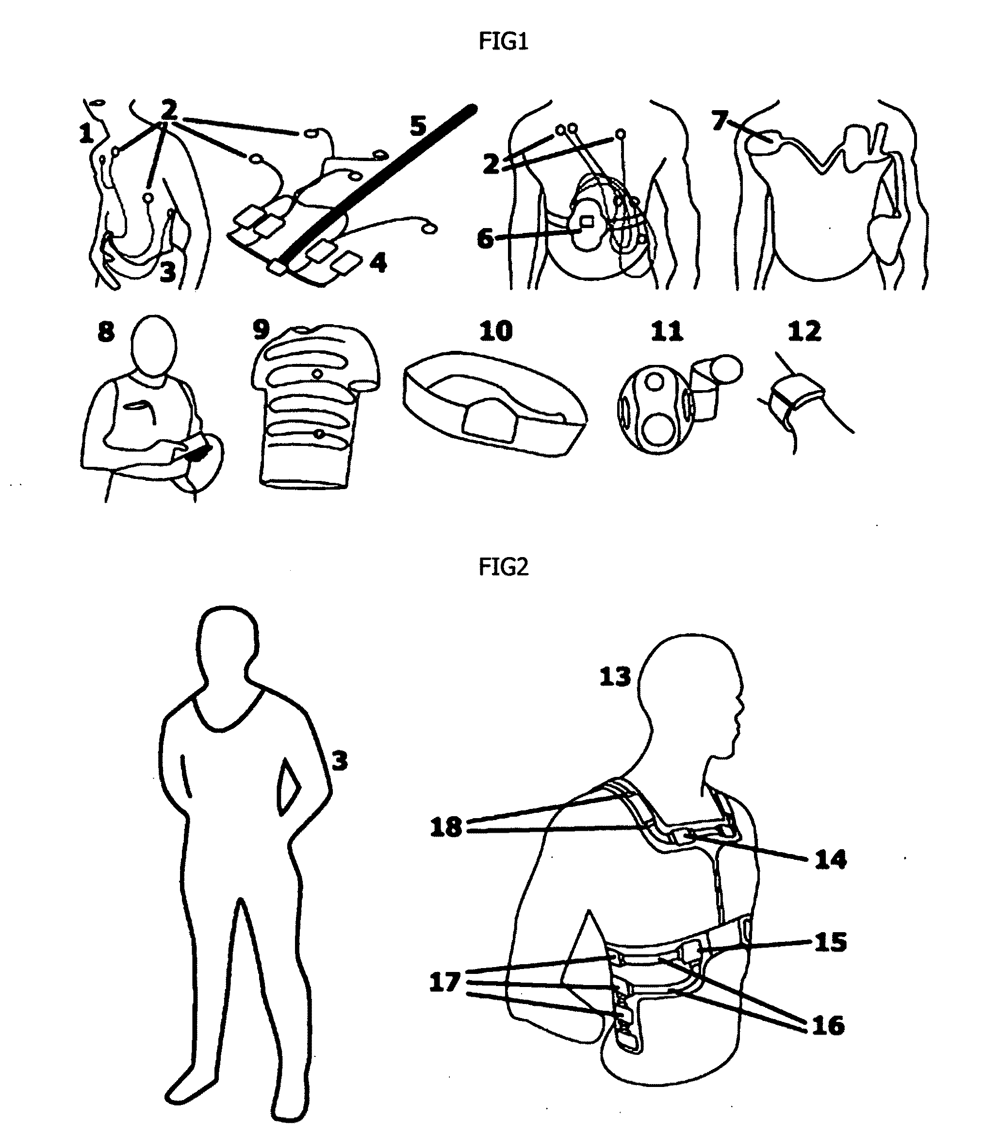
[0038]FIG. 1 shows a wearable electronic health 1 monitor worn by NASA astronauts during the Apollo moon missions. A series of electrical body sensors (electrodes) 2 are shown attached to the upper torso. These are worn underneath the tight fitting liquid cooling ventilation garment 3. Also shown are the electronic circuit modules 4 strung around the waist in a belt like fashion and connected through a multi-core electrically conductive cable 5. The electronic circuit modules 4 are condensed into a smaller unit 6 shown attached to the frontal chest area of the Lifeguard wearable electronic health monitor. ECG electrodes 2 are substituted for a partially integrated set of electrodes 7 believed from the Nexan company. The Lifeshirt wearable electronic health monitor from the Vivometrics company is shown 8, a shirt consisting of woven wires and optical fibers from the Sensatex company is shown 9, a waistband from the Zephyr company is shown 10, an armband from the Bodymedia company is ...


PUM


Abstract

This document describes the design and control of a modular wearable electronic system that integrates an electrical interconnection harness, human body electrode modules, physiological sensor modules, electronic circuit modules, control software, and power supply modules into a single assembly. The design is intended to allow medical sensors and electronic circuits from different manufacturers to be connected into the system with relative ease. This system will enable a platform that can be expanded to incorporate many different kinds of physiological sensors and electronic circuits as and when they become available. It will also allow for different sizes of wearable electronic system to be constructed by simply changing the lengths and shapes of the electrical interconnections between the electrical modules.

Description

CROSS-REFERENCE TO RELATED APPLICATIONS[0001]Provisional Patent Application No. 61 / 058,539.STATEMENT REGARDING FEDERALLY SPONSORED RESEARCH OR DEVELOPMENT[0002]Not applicable.REFERENCE TO SEQUENCE LISTING, A TABLE OR A COMPUTER PROGRAM LISTING COMPACT DISC APPENDIX:[0003]Not applicable.BACKGROUND OF THE INVENTION[0004]An early example of a portable wearable electronic system is the battery powered heated sock used for warming feet in old climates. More recent examples have been used for monitoring the personal health of an individual. During the NASA Apollo space missions of the 1960s, a bio-belt consisting of various electronic processing boxes was attached around the waist and used to measure the heart electro-cardiogram (ECG) signals of the astronauts via wire cables attached to skin electrodes positioned across the upper body surface. Highly accurate ECG measurements can require up to 10 separate wire cables connected to the body making the attachment procedure slow and the dang...

Claims


Application Information

Patent Timeline
Patent Type & Authority Applications(United States)
IPC IPC(8): A61B5/00A61B5/04
CPCA61B5/0017A61B5/04085A61B5/6839A61B5/6831A61B5/6804H01R13/6584A61B5/282
Inventor BELL, JONATHAN ARNOLD
Owner BELL JONATHAN ARNOLD
Why Eureka
Try Eureka