Radar measurement method with different fields of view

Active Publication Date: 2017-05-11
ROBERT BOSCH GMBH
View PDF10 Cites 8 Cited by
  • Summary
  • Abstract
  • Description
  • Claims
  • Application Information

AI Technical Summary

Benefits of technology

[0012]An object of the present invention is to provide a method of the kind which permits better utilization of an available cycle time for sampling the different fields of view. When objects are to be localized in different but overlapping fields of view, for example in a field of view

Problems solved by technology

A measurement of the frequency difference on a single ramp therefore does not yet permit a determination of the distance and the relative velocity, but instead supplies only a linear relationship between those variables.
The code multiplexing method requires a great deal of outlay, however, and enables only limited signal orthogonality.
With the frequency multiplexing method the disadvantage exists that the phase and the Doppler shift are dependent on the respective wavelength.
W

Method used


Image

  • Radar measurement method with different fields of view
  • Radar measurement method with different fields of view
  • Radar measurement method with different fields of view

Examples


Embodiment Construction

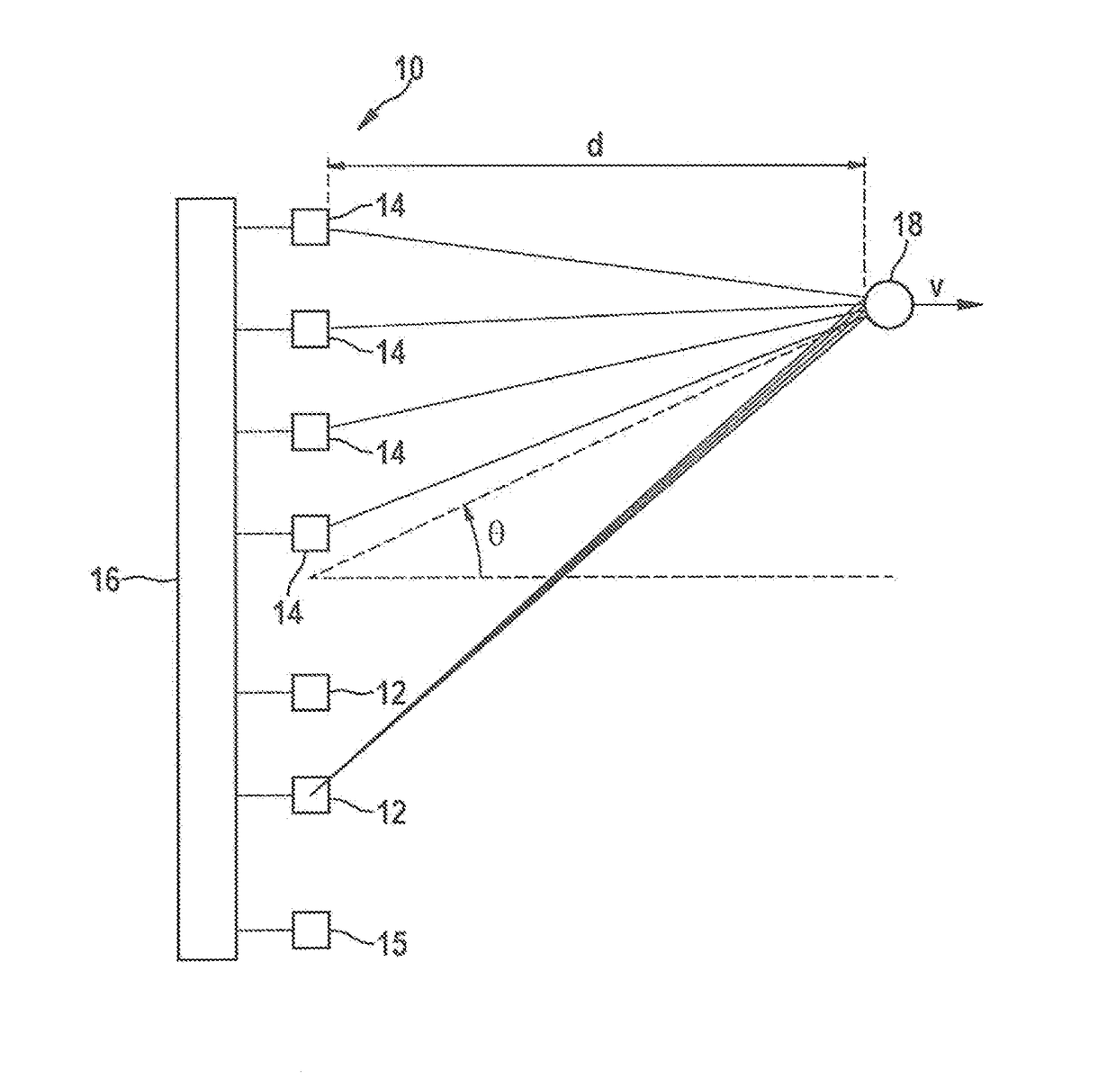
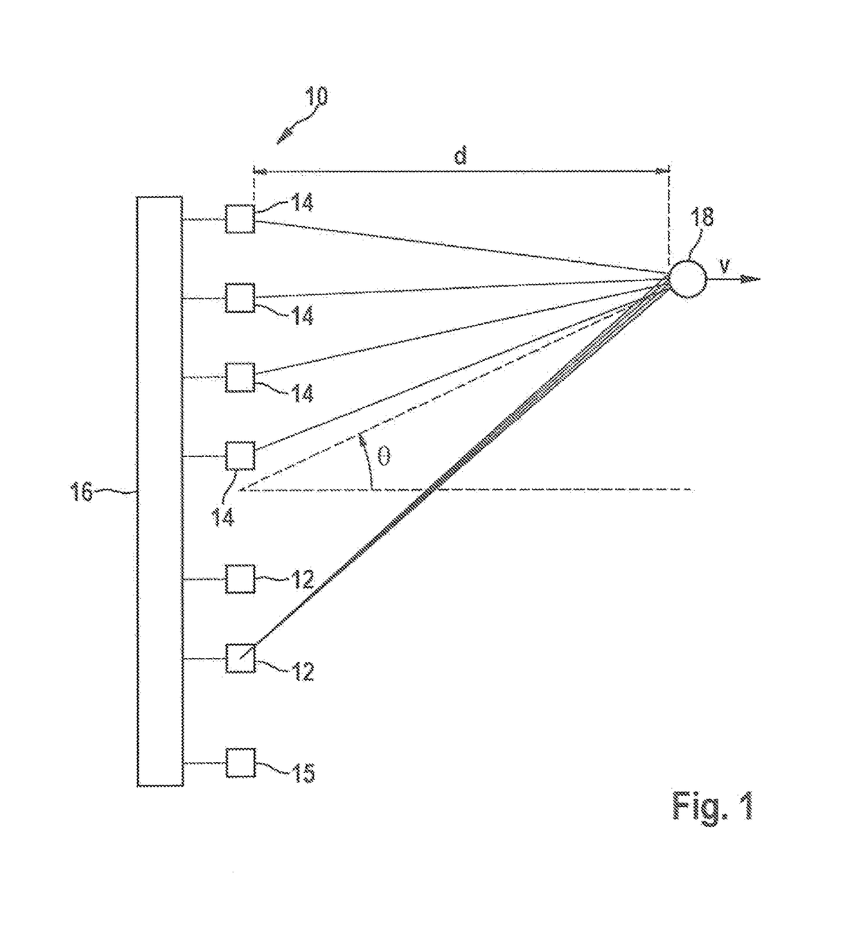
[0062]FIG. 1 is a diagram of a simple example of a (MIMO) FMCW radar sensor 10 that in this example has two transmitting antennas 12 and four receiving antennas 14 for MIMO measurements in a first field of view, as well as a further antenna 15 having a different field of view. Larger numbers of antennas are possible in practice. Transmitting antennas 12, 15 are powered by a control and evaluation unit 16 and emit radar signals that are reflected at an object 18 and received by each of the receiving antennas 14. The field of view of transmitting antenna 15 has a greater range and a narrower aperture angle than the field of view of transmitting antennas 12. The transmitting and receiving antennas can each be made up of a patch antenna array.

[0063]The received signals are mixed down to baseband signals and evaluated in control and evaluation unit 16. Radar sensor 10 is installed, for example, at the front in a motor vehicle and serves to measure distances d, angles, and relative veloci...


PUM


Abstract

An FMCW radar sensor and a method for localizing a radar target, in which FMCW radar measurements are performed with transmitting antennas having different fields of view which differ in terms of an aperture angle and/or a range, the measurements each encompassing temporally interleaved sequences of ramps, and measurements with different fields of view being temporally interwoven with one another; ambiguous values for the relative velocity of the radar target being determined from a position of a peak in a two-dimensional spectrum; phase relationships between spectral values of spectra being checked for agreement with phase relationships expected for several of the determined values of the relative velocity; and on the basis thereof an estimated value for the relative velocity of the radar target being selected from the determined periodic values of the relative velocity.

Description

FIELD[0001]The present invention relates to a method for localizing a radar target in which FMCW radar measurements are performed with transmitting antennas having different fields of view which differ in terms of an aperture angle and / or a range, received signals being mixed down to baseband signals.BACKGROUND INFORMATION[0002]The present invention relates in particular to a method of this kind in which, for at least two of the fields of view, the respective measurement is an angularly resolving measurement that is performed with different selections of several antennas used for transmission and / or for reception, a search for peaks in two-dimensional spectra of the baseband signals of the measurements of the respective fields of view being carried out in order to localize radar targets, and an angular position of a radar target localized in a respective field of view being determined on the basis of amplitudes and / or phases at the position of a peak, corresponding to the radar targ...

Claims


Application Information

Patent Timeline
IPC IPC(8): G01S13/02G01S13/42G01S13/58G01S13/931
CPCG01S13/0209G01S13/931G01S13/42G01S13/584G01S7/354G01S13/32G01S13/343G01S13/536G01S2013/0245G01S7/356G01S13/424
Inventor SCHOOR, MICHAELLOESCH, BENEDIKT
Owner ROBERT BOSCH GMBH
Why Eureka
Try Eureka