
Apparatus and method for modelling a modular multilevel converter in an electronic simulator

a multi-level converter and electronic simulator technology, applied in the field of real-time simulators, to achieve the effect of increasing simulation speed without downgrading model detail and precision

Active Publication Date: 2017-05-11
OPAL RT TECH INC
View PDF8 Cites 42 Cited by
  • Summary
  • Abstract
  • Description
  • Claims
  • Application Information

AI Technical Summary

Benefits of technology

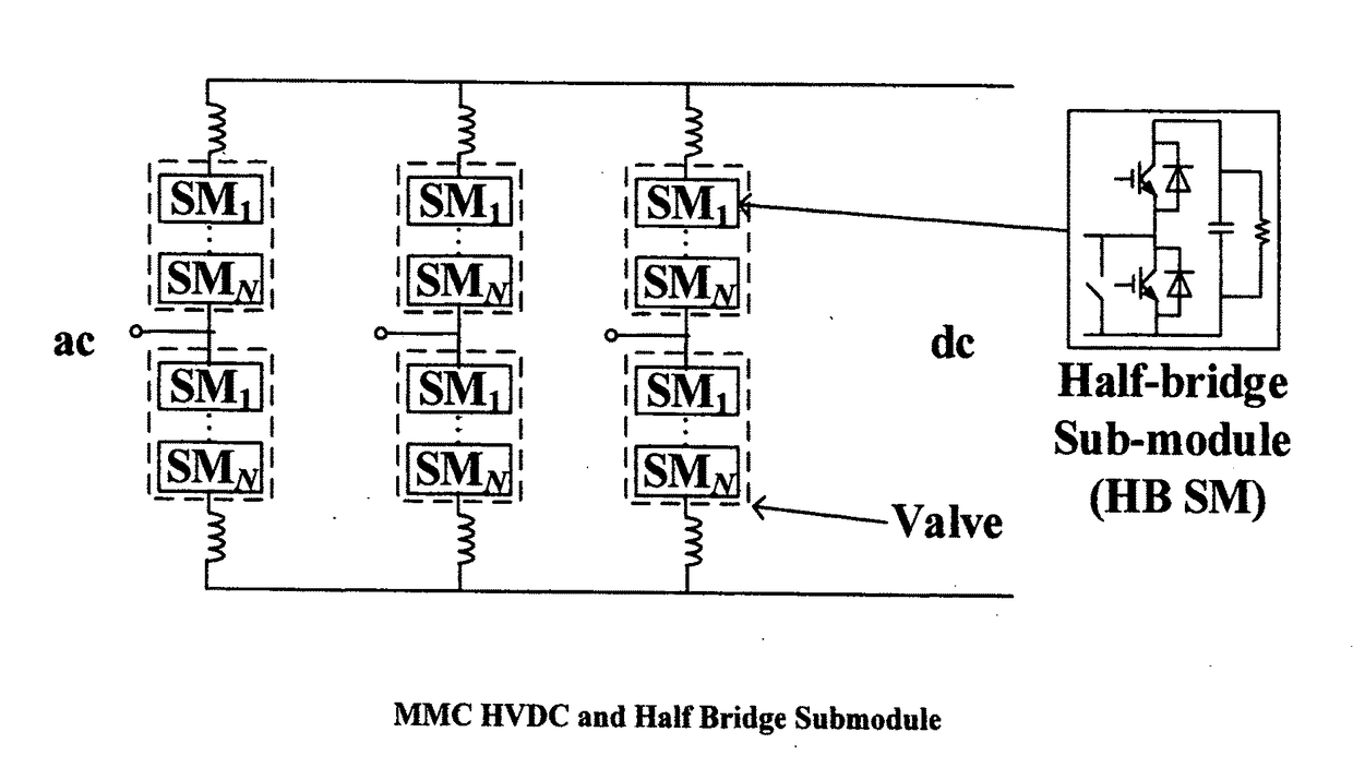
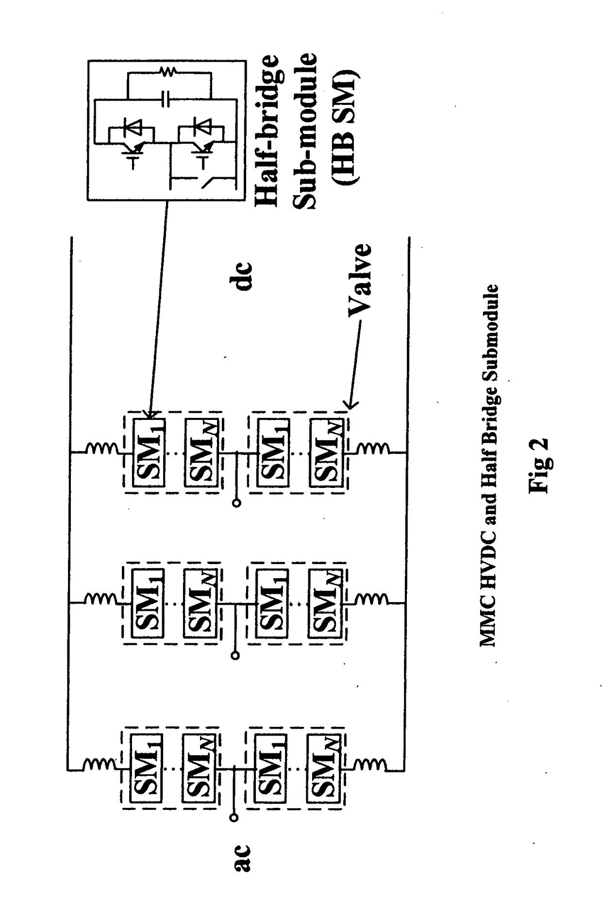
The present invention relates to an apparatus and method for simulating a modular multilevel converter (MMC) system. The invention focuses on finding the preferred / right equivalent circuit, so that the MMC system valves can be simulated in parallel, faster, and without loss of necessary details. The invention provides a method for ascertaining the status of each SM based on its mode and representing each SM by an equivalent circuit, solving a predetermined capacitor-voltage-equation to arrive at the capacitor voltage, and compiling voltage values of source voltages for each mode. The technical effect of the invention is to increase the simulating speed of the MMC system without sacrificing model-detail and precision.

Problems solved by technology

Conventional simulators or simulation programs have deficiencies in simulating a power system comprising a MMC with fast or real time simulation speed.

Method used


Image

  • Apparatus and method for modelling a modular multilevel converter in an electronic simulator
  • Apparatus and method for modelling a modular multilevel converter in an electronic simulator
  • Apparatus and method for modelling a modular multilevel converter in an electronic simulator

Examples


Embodiment Construction

[0037]A detailed description of one or more embodiments of the invention is provided below in the context of the accompanying figures that illustrate by way of example the principles of the invention. While the invention is described in connection with such embodiments, it should be understood that the invention is not limited to any particular embodiment. On the contrary, the scope of the invention is limited only by the appended claims and the invention encompasses numerous alternatives, modifications and equivalents. For the purpose of example, numerous specific details are set forth in the following description in order to provide a thorough understanding of the present invention.

[0038]The present invention may be practiced according to the claims without some or all of these specific details. For purposes of clarity, technical material that is known in the technical fields related to the invention has not been described in detail so that the present invention is not unnecessari...


PUM


Abstract

Method and apparatus for simulating a MMC system in an electronic simulator uses a computing unit and a connected input / output interface. The electronic simulator comprises a simulation model of a modular multilevel converter (MMC) system including at least one MMC valve, each MMC valve including a plurality of connected converter-submodules (SMs), each SM preferably comprising at least two controlled switches, a capacitor and auxiliary switches. The inventive approach replaces each MMC valve by an equivalent circuit whereby each SM in the valves may be solved separately. Multiple computing units are used to simulate those SMs in parallel, thus achieving fast or real-time simulation speed. The computing unit may comprise multiple computing means using CPU cores, FPGA or GPU cores and combinations thereof. The present inventive method keeps the model-detail including its precision, and enables a real time simulator to achieve fast or real-time speed for very large MMC system-simulations.

Description

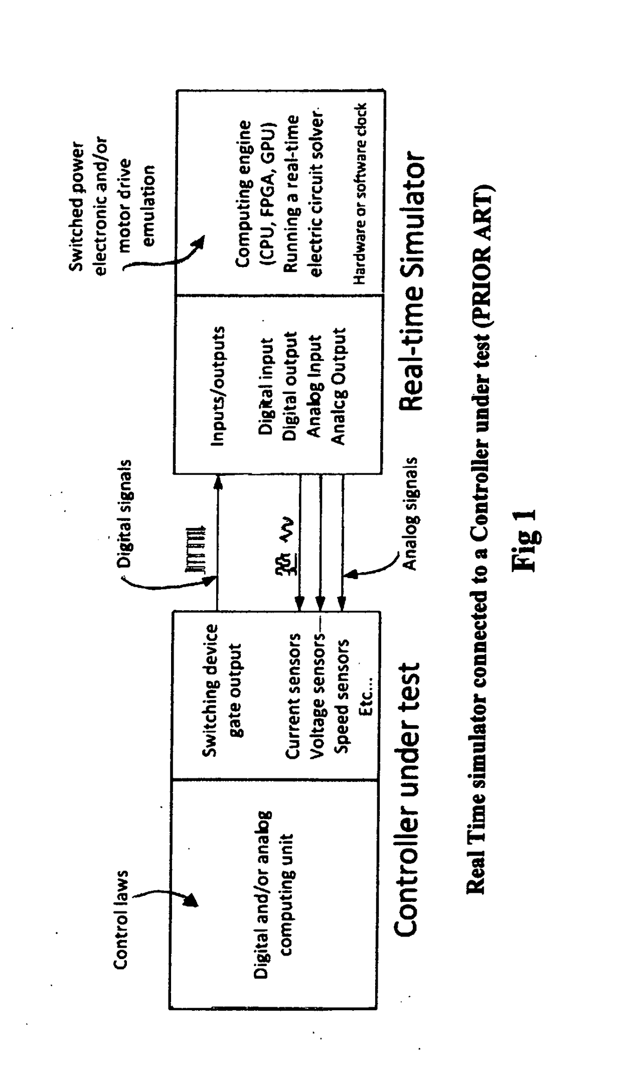
RELATED APPLICATIONS[0001]This application claims priority from U.S. provisional application 62 / 285,835 filed on 10 Nov. 2015, the contents of which are incorporated herein by reference.BACKGROUND OF THE INVENTION[0002]A real-time simulator is a device that emulates the real-time behaviour of a system or apparatus at real-life speed. Real-time simulators comprise elements that are typically based on computers or similar digital computing devices that compute the apparatus-governing-equations, which typically include a set of Differential-Algebraic Equations (DAEs). Practically, the system / apparatus may comprise ‘controlled devices’, meaning that they normally work in conjunction with a controller. The controller has the objective of effectively controlling the apparatus within certain objectives and requirements. In real life, the performance of the device (also known as the ‘plant’) is controlled by accepting the commands of the controller. The controller adjusts its commands by re...

Claims


Application Information

Patent Timeline
IPC IPC(8): G06F17/50G06F17/11
CPCG06F17/11G06F17/5009G06F30/331G06F30/367H02M7/219
Inventor LI, WEI
Owner OPAL RT TECH INC
Learn More