Sound attenuation

a technology of attenuation and sound, applied in the direction of sound producing devices, instruments, building components, etc., can solve the problems of not wholly efficient sound absorption materials, and increased size and/or weigh

Inactive Publication Date: 2017-05-11
CARBON AIR
View PDF15 Cites 14 Cited by
  • Summary
  • Abstract
  • Description
  • Claims
  • Application Information

AI Technical Summary

Benefits of technology

[0013]It is an aim of the present invention to at

Problems solved by technology

However, the building industry is strongly inclined to specify established materials with known properties wherever possible which are typically not wholly efficient sound absorbing materials.
However, if a single solid partition is divided into two or more partition leaves with the same mass overall, the transmission loss achieved is generally larger than that of the single partition.
However, an increase in size and/or weight is generally not desirable particularly in building and vehicle applications.
Furthermore, deep cavities are inefficient in terms of building or vehicle packaging and acoustic treatment is often required within existing standard panel gaps, particularly in the retrofit building market and in the conversion of buildings from single to multiple occupancy.
Also, it is often not possible to alter ceiling, floor or party wall thicknesses to achieve the required acoustic transmission loss performance without extensive and expensive redevelopment of the entire building structure, with the introduction of expensive false ceilings and floating floo

Method used


Image

  • Sound attenuation
  • Sound attenuation
  • Sound attenuation

Examples


Embodiment Construction

[0161]In the drawings like reference numerals refer to like parts.

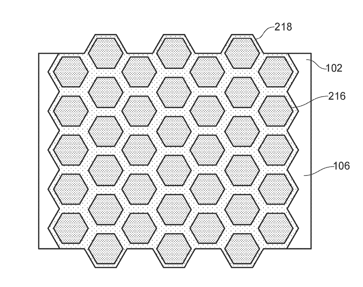
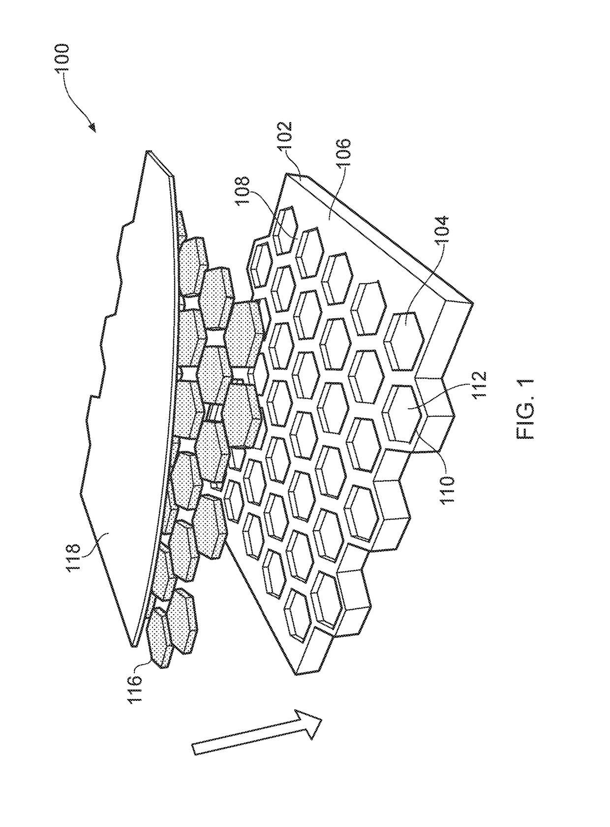
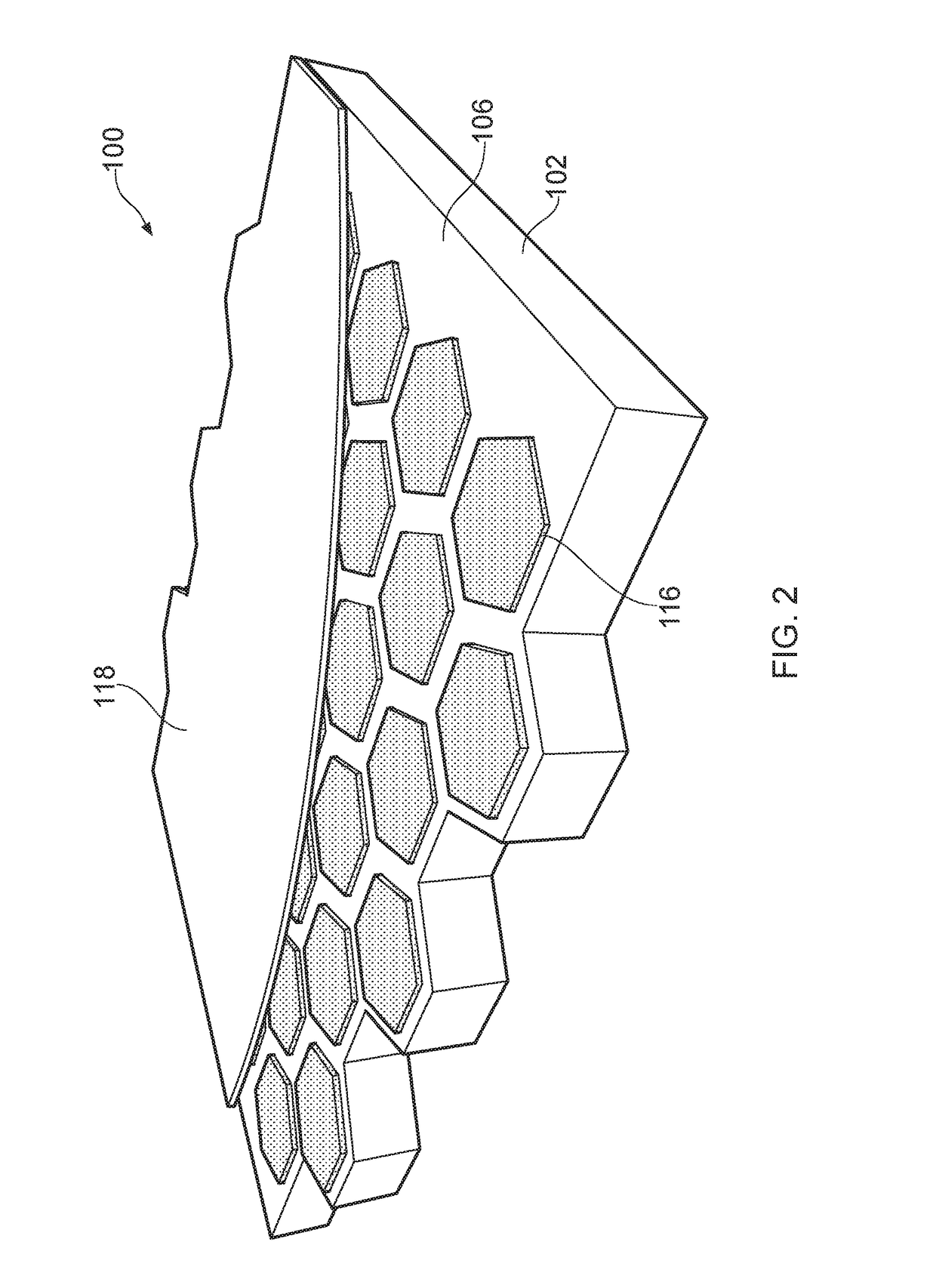
[0162]FIG. 1 illustrates a sound attenuating apparatus 100 according to certain embodiments of the present invention. The apparatus includes a foam substrate layer 102. This is a 2-scale heterogeneous material. Aptly, the substrate could be another type of 2-scale heterogeneous material, such as a foam, mineral wool, glass wool, or the like. Aptly, the substrate may be a porous non-woven material. The substrate has a number of recesses 104 extending inwardly from an outer surface 106 of the substrate layer 102. The outer surface 106 is a sound receiving surface, i.e. a surface of the substrate layer that in use is arranged to face the approaching sound waves. The thickness of the substrate layer 102 is about around 20 cm but may vary depending on the technical application and sound attenuation performance required. For example, the thickness of the substrate layer 102 may be about around 1 to 100 cm, aptly about aroun...


PUM


Abstract

The present invention provides a sound attenuating apparatus including a substrate element comprising at least one first heterogeneous material, and at least one region comprising at least one further heterogeneous material at least partially located in the substrate element, wherein the at least one further heterogeneous material has at least one more scale of heterogeneity than the at least one first heterogeneous material. The present invention provides a method and apparatus for attenuating sound through a cavity construction in buildings and vehicles or the like, wherein the method comprises locating at least one region of adsorptive material in a cavity defined between a first wall region and a further wall region to attenuate sound transmission across the wall regions.

Description

FIELD OF THE INVENTION[0001]The present invention relates to a method and apparatus for attenuating sound and in particular, but not exclusively, the present invention relates to a method, use and apparatus for attenuating sound through a cavity construction in buildings and vehicles or the like. The present invention also relates to the formation and use of a sound attenuating body for attenuating sound in buildings and vehicles or the like.[0002]The building and automotive industries in particular are driving the development of new materials and technologies for attenuating sound (or more specifically ‘noise’ which can be defined as unwanted sound) more efficiently and particularly at low frequencies of less than 400 Hz. For example, sound attenuation is becoming increasingly important to reduce, or even eliminate, the amount of noise associated with the powertrain, rolling surfaces and air aerodynamic effects of a vehicle, and minimising the amount of such noise being transmitted...

Claims


Application Information

Patent Timeline
IPC IPC(8): G10K11/172G10K11/168
CPCG10K11/168G10K11/172E04B1/84E04B2001/748E04B2001/848
Inventor COAKLEY, JOHN FITZGERALDVENEGAS, RODOLFO GUSTAVOMOORHOUSE, ANDREW THOMAS
Owner CARBON AIR
Why Eureka
Try Eureka