Mold Cleaning System

Active Publication Date: 2017-05-18
YOKOHAMA RUBBER CO LTD
View PDF2 Cites 5 Cited by
  • Summary
  • Abstract
  • Description
  • Claims
  • Application Information

AI Technical Summary

Benefits of technology

[0009]According to the present technology, when cleaning a mold, three-dimensional image data of a molding surface of the mold to be cleaned is acquired by a camera. As such, the shape of the molding surface of the mold can be accurately grasped at the time of cleaning. Thus, it is no longer required to perform manual operations for invoking the shape data of the molding surface of the mold to be cleaned from a database and to check the correspondence relation between the actual mold and the shape data every time the cleaning is performed. Also, since the laser head is moved along the molding surface on the basis of the acquired image data while irradiating with the laser beam to clean the molding surface, it is possible to prevent scratches on the molding surface while efficiently removing the dirt therefrom without requiring a manual operation by a person, even for molds having complicated molding-surface shapes. Additionally, even if the shape of the molding surface changes with time, there are advantages compared to a case where pre-recorded shape data of the molding surface is used in that the molding surface can be more completely cleaned without leaving traces of dirt because the image data of the molding surface is acquired at the time of cleaning.
[0010]Here, for example, the mold cleaning system may be configured to grasp a cleaning state of the molding surface on the basis of three-dimensional image data of a cleaned molding surface of a mold acquired by the camera; store the grasped cleaning state and position information of the molding surface in the control device; and for positions on the molding surface in which the grasped cleaning state does not satisfy a preset standard, perform cleaning again by irradiating with the laser beam from the laser head. With this configuration, only the positions (range) that are particularly dirty are re-cleaned later, which is advantageous for removing t

Problems solved by technology

Since the dirt gradually accumulates as the mold is used repeatedly, leaving the dirt as it is negatively impacts the quality of the products to be vulcanized.
However, an area that the plasma cleaning method can clean in a unit time is small.
However, the molding surface of the mold is not always formed in the same shape but is formed i

Method used


Image

  • Mold Cleaning System
  • Mold Cleaning System
  • Mold Cleaning System

Examples


Example

[0021]A mold cleaning system of the present technology will now be described on the basis of the embodiments illustrated in the drawings.

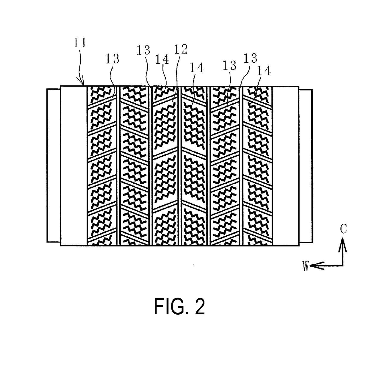
[0022]Although a tire vulcanization mold is to be cleaned in the following description, the present technology can also be used to clean molds for vulcanizing other rubber products than tires.

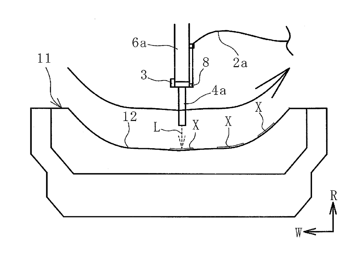
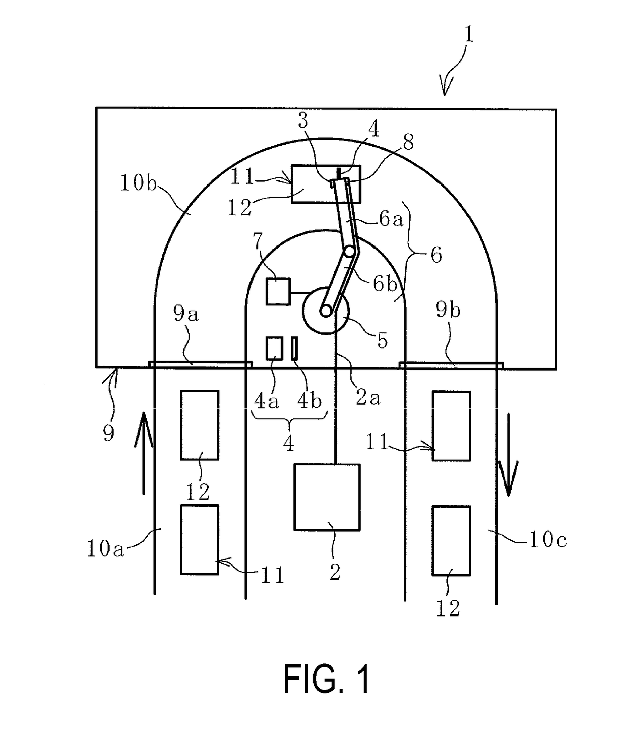
[0023]A mold cleaning system 1 of the present technology illustrated in FIG. 1 is provided with a laser oscillator 2, a laser head 4, an arm 6 to which the laser head 4 is attached, a control device 7 that controls the motion of the arm 6, and a camera 3. The camera 3 acquires three-dimensional image data of a molding surface 12 of a mold 11. In this embodiment, the mold cleaning system 1 is further provided with a temperature sensor 8 that successively detects a temperature of the molding surface 12 that is irradiated with a laser beam L. The camera 3 and the temperature sensor 8 are attached to a tip of the arm 6, and the image data acquired by the camera 3 ...


PUM

PropertyMeasurementUnit
Temperatureaaaaaaaaaa

Abstract

Provided is a mold cleaning system. When cleaning a mold, the mold cleaning system acquires three-dimensional image data of a molding surface of the mold by a camera and, on the basis of the acquired image data, the mold cleaning system controls the movement of arms using a control device, moves a laser head along the molding surface while irradiating with a laser beam supplied by a laser oscillator and, as a result, removes dirt adhered to the molding surface.

Description

TECHNICAL FIELD[0001]The present technology relates to a mold cleaning system; and particularly relates to a mold cleaning system which makes it possible to prevent scratches on a molding surface while efficiently removing dirt therefrom without requiring a manual operation by a person, even for molds having complicated molding-surface shapes.BACKGROUND ART[0002]Dirt derived from rubber components or compounding agents is adhered slightly to a molding surface of a mold for vulcanizing rubber products such as tires every time the vulcanization is performed. Since the dirt gradually accumulates as the mold is used repeatedly, leaving the dirt as it is negatively impacts the quality of the products to be vulcanized. Thus, as appropriate, the dirt needs to be removed by cleaning the molding surface. Examples of known mold cleaning methods include a shot blasting cleaning method, a laser beam cleaning method, and a plasma cleaning method.[0003]With the shot blasting cleaning method, the ...

Claims


Application Information

Patent Timeline
IPC IPC(8): B29D30/06G05D3/12B29C33/72B08B7/00B23K26/08B23K26/36
CPCB29D30/0662B23K26/0884B23K26/36B29C33/72B29K2021/00G05D3/12B29C2033/705B29D2030/0663B29L2030/00B08B7/0042B23K26/08B29C33/02
Inventor MATSUMURA, KENSUKEWATANABE, MASAYIKIMIYAZAKI, YUSAKU
Owner YOKOHAMA RUBBER CO LTD
Why Eureka
Try Eureka