Device and method for influencing the temperatures in inner ring segments of a gas turbine

a technology of inner ring segments and gas turbines, which is applied in the direction of engine fuction, leakage prevention, air transportation, etc., can solve the problems of increasing the weight of inner segments, still leakage of hot gas, and increasing manufacturing efforts, so as to prevent the formation of cracks, reduce the effect of heat loss and efficient and low-loss mixing

Active Publication Date: 2017-05-18
MTU AERO ENGINES GMBH
View PDF44 Cites 3 Cited by
  • Summary
  • Abstract
  • Description
  • Claims
  • Application Information

AI Technical Summary

Benefits of technology

[0021]It is advantageous to divide the cooling air and the portion of hot gas into subflows during flow into the mixing space, because mixing individual subflows is thermally more efficient than mixing an undivided flow of cooling air with a not further divided portion of the hot gas. Particularly efficient and low-loss mixing can be achieved when the first subflows of hot gas and the second subflows of cooling air flow in the same direction. During mixing of the first subflows of hot gas and the second subflows of cooling air, the temperatures in the inner ring segments are evened out. Evening out the temperatures in the inner ring segments prevents the formation of cracks in the inner ring segments, thereby preventing potential failure of the inner ring segments. Thus, the first subflows of hot gas are used in a purposeful manner to equalize temperatures. In conventional arrangements, such subflows of hot gas would have been considered merely as leakage.
[0022]In a practical embodiment of the present invention, the second subflows of cooling air enter the mixing space upstream of or at the same position as the first subflows of hot gas in the circumferential direction of the gas turbine. If the second subflows of cooling air enter the mixing space upstream of the first subflows of hot gas, then the ends of the first ship laps are cooled, thereby preventing peak thermal loads in the first ship laps. If the second subflows of cooling air enter the mixing space at the same position as the first subflows of hot gas, then uniform mixing occurs, which is favorable for the temperature transfer to the inner ring segments. In another embodiment of the present invention, the mixed flow passes through the mixing space in the circumferential direction of the gas turbine. Passage of flow in the circumferential direction has the advantage that the first subflows of hot gas and the second subflows of cooling air flow along the inner ring segments, a temperature of a mixed flow of the first subflows of hot gas and the second subflows of cooling air being convectively transferred to the inner ring segments, and the thermal gradients within the inner ring segments being minimized. In a practical embodiment of the present invention, the mixed flow exits through gaps in axially downstream holders of the inner ring segments. In this way, the mixed flow of the first subflows of hot gas and the second subflows of cooling air can be led out of the mixing space in a simple manner.

Problems solved by technology

This results in high temperature gradients within the inner segments, causing cracks.
However, there is still leakage of hot gas, whereby the circumferential end portions of the inner segments are heated to a greater degree than the central regions.
Alternatively, the inner segments are reinforced, which, however, increases the weight of the inner segments.
The disadvantage here is the complex geometry of the end portions of the inner shroud segments, which requires increased manufacturing effort.
It is a disadvantage here that the inner and outer cover segments have a very high degree of structural complexity, which requires increased manufacturing effort.
Here too, the structural geometry is complex and requires considerable assembly effort.

Method used


Image

  • Device and method for influencing the temperatures in inner ring segments of a gas turbine
  • Device and method for influencing the temperatures in inner ring segments of a gas turbine

Examples


Embodiment Construction

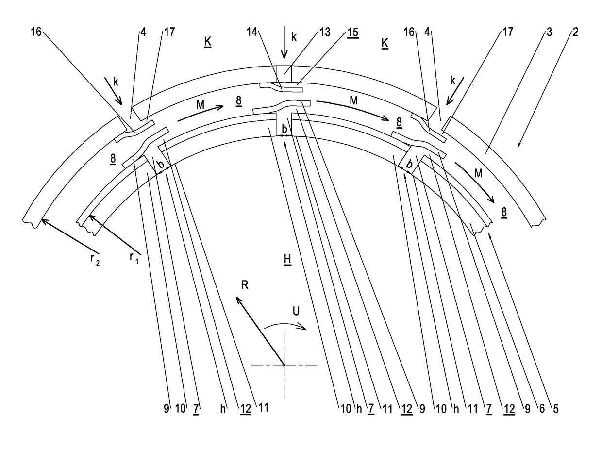
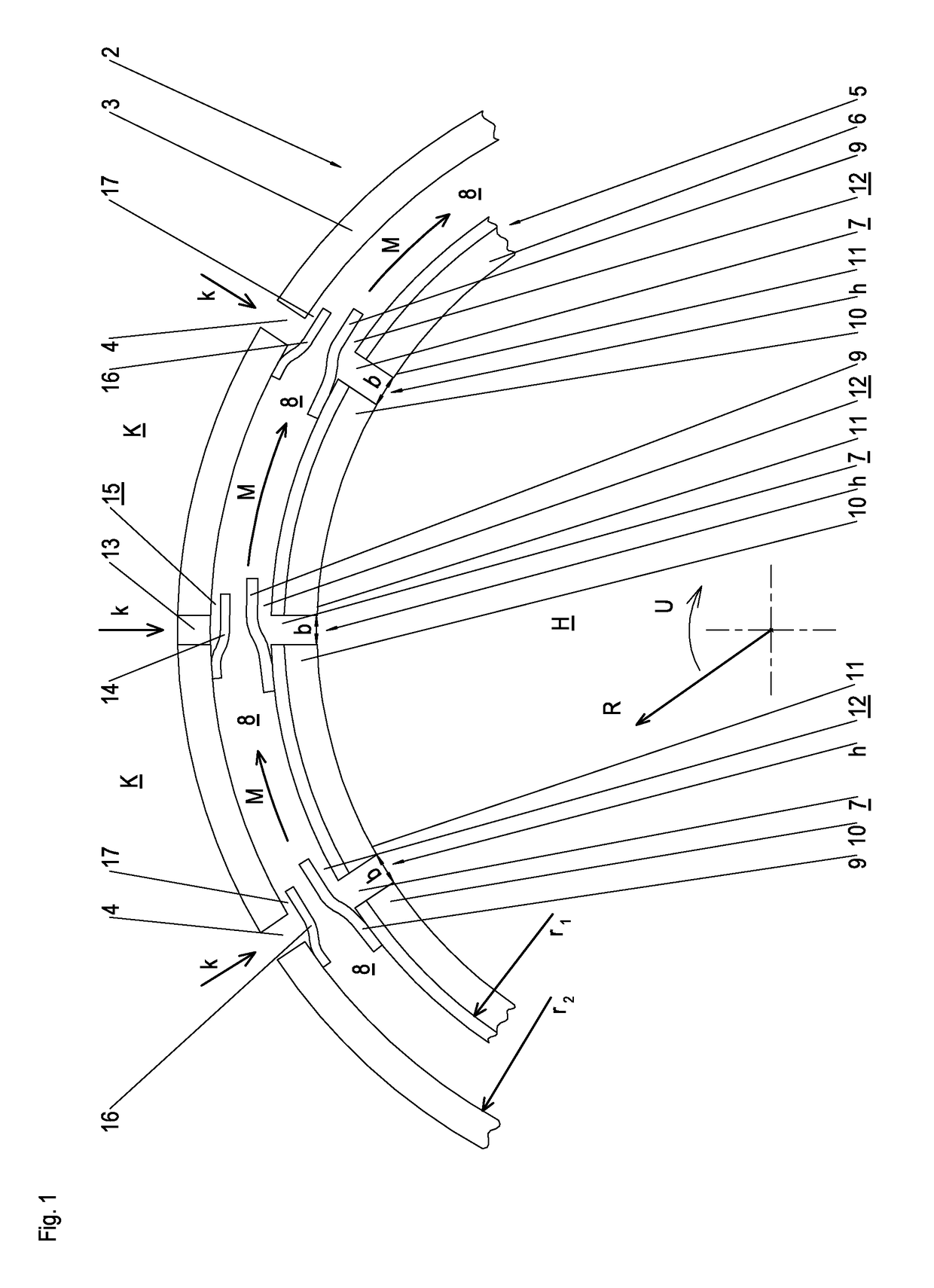
[0024]FIG. 1 schematically shows in cross section a device 1 having an outer shell assembly 2 and an inner shell assembly 5 of a not further shown thermal turbomachine which will be described below as a gas turbine in accordance with the exemplary embodiment. An outer shell assembly 2 and an associated inner shell assembly 5 are disposed between each two adjacent stator vane rings. Outer shell assembly 2 includes at least two outer ring segments 3. In FIG. 1, one outer ring segment 3 is illustrated in detail and two other outer ring segments 3 are depicted fragmentarily. Inner shell assembly 5 includes a plurality of inner shell segments 6, of which four inner shell segments 6 are shown in FIG. 1. The number of inner ring segments 6 is greater than the number of outer ring segments 3. In the figure, the ratio of the number of inner ring segments 6 to the number of outer ring segments 3 is two to one.

[0025]Inner ring segments 6 are curved in circumferential direction U of the gas tur...


PUM


Abstract

A device for influencing the temperatures in inner ring segments of a gas turbine is provided, which includes in the circumferential direction of the gas turbine, at least one outer shell assembly having a plurality of outer ring segments and at least one inner shell assembly having a plurality of inner ring segments. The inner ring segments are equal to or greater in number than the outer ring segments. An outer ring segment gap is between each two adjacent outer ring segments. An inner ring segment gap is between each two adjacent inner ring segments. An outer ring segment gap, or at least a radial cooling air passage, is located opposite each inner ring segment gap in the radial direction of the gas turbine.

Description

[0001]This claims the benefit of German Patent Application DE102015215144.1, filed Aug. 7, 2015 and hereby incorporated by reference herein.[0002]The present invention relates to a device for influencing the temperatures in inner ring segments of a gas turbine, and to a method for influencing the temperatures in inner ring segments of a gas turbine using the device.BACKGROUND[0003]In gas turbines, a hot gas flow is passed between two stator vane rings within a shroud ring. The shroud ring includes an outer shell and an inner shell, each of which are segmented. The number of outer segments is usually greater than the number of inner segments. Generally, gaps between the outer segments are located opposite central regions of inner segments. The gaps allow for thermal expansion of the outer segment and the inner segments. During operation, a portion of the hot gas flows into the gaps between the inner segments and heats up the end portions of the inner segments. The central regions are...

Claims


Application Information

Patent Timeline
Patent Type & Authority Applications(United States)
IPC IPC(8): F01D11/00B64D27/10F01D25/12
CPCF01D11/003F01D25/12F05D2260/20F05D2240/55B64D27/10F01D25/14F01D25/26F05D2240/11Y02T50/60
Inventor LAUER, CHRISTOPH
Owner MTU AERO ENGINES GMBH
Why Eureka
Try Eureka