Method and system for vacuum generation using a throttle body comprising a slidable throttle valve

Inactive Publication Date: 2017-05-18
FORD GLOBAL TECH LLC
View PDF9 Cites 10 Cited by
  • Summary
  • Abstract
  • Description
  • Claims
  • Application Information

AI Technical Summary

Benefits of technology

The patent describes a new approach for generating vacuum in an engine using a throttle valve. By adjusting the size and shape of the throttle valve, the amount of vacuum generated can be increased. This allows for better control of airflow and compensation for airflow errors. By combining the functions of a throttle and an aspirator into a single throttle valve, additional control valves and parts may not be needed, reducing manufacturing expenses and packaging issues. Overall, this approach provides a more efficient and cost-effective solution for generating vacuum in engines.

Problems solved by technology

However, as recognized by the inventors herein, in the approaches described above, the vacuum generation potential of the throttle may be limited.
However, fabricating these control bores may result in significant modifications to the design of the intake passage which can increase related expenses.
In the approaches that use one or more aspirators to generate vacuum, additional expenses may be incurred because of individual parts that form the aspirator including nozzles, mixing and diffusion sections, and check valves.
Further, at idle or low load conditions, it may be difficult to control the total air flow rate into the intake manifold since the flow rate is a combination of leakage flow from the throttle and airflow from the aspirator.
Typically, an aspirator shut off valve (ASOV) may be included along with the aspirator to control airflow but with added cost.
Further, installing aspirators in the intake can lead to constraints on space availability as well as packaging issues.
As an example, the vacuum generation potential of the throttle is limited.
As an example, the size of the perforations may be limited due to the width of the throttle valve, and therefore the vacuum generation potential of the throttle is limited.
However, increasing the size of the perforations may result in increases of the size and of the throttle which may result in significant modifications to the design of the intake passage which can increase related expenses.

Method used


Image

  • Method and system for vacuum generation using a throttle body comprising a slidable throttle valve
  • Method and system for vacuum generation using a throttle body comprising a slidable throttle valve
  • Method and system for vacuum generation using a throttle body comprising a slidable throttle valve

Examples


first embodiment

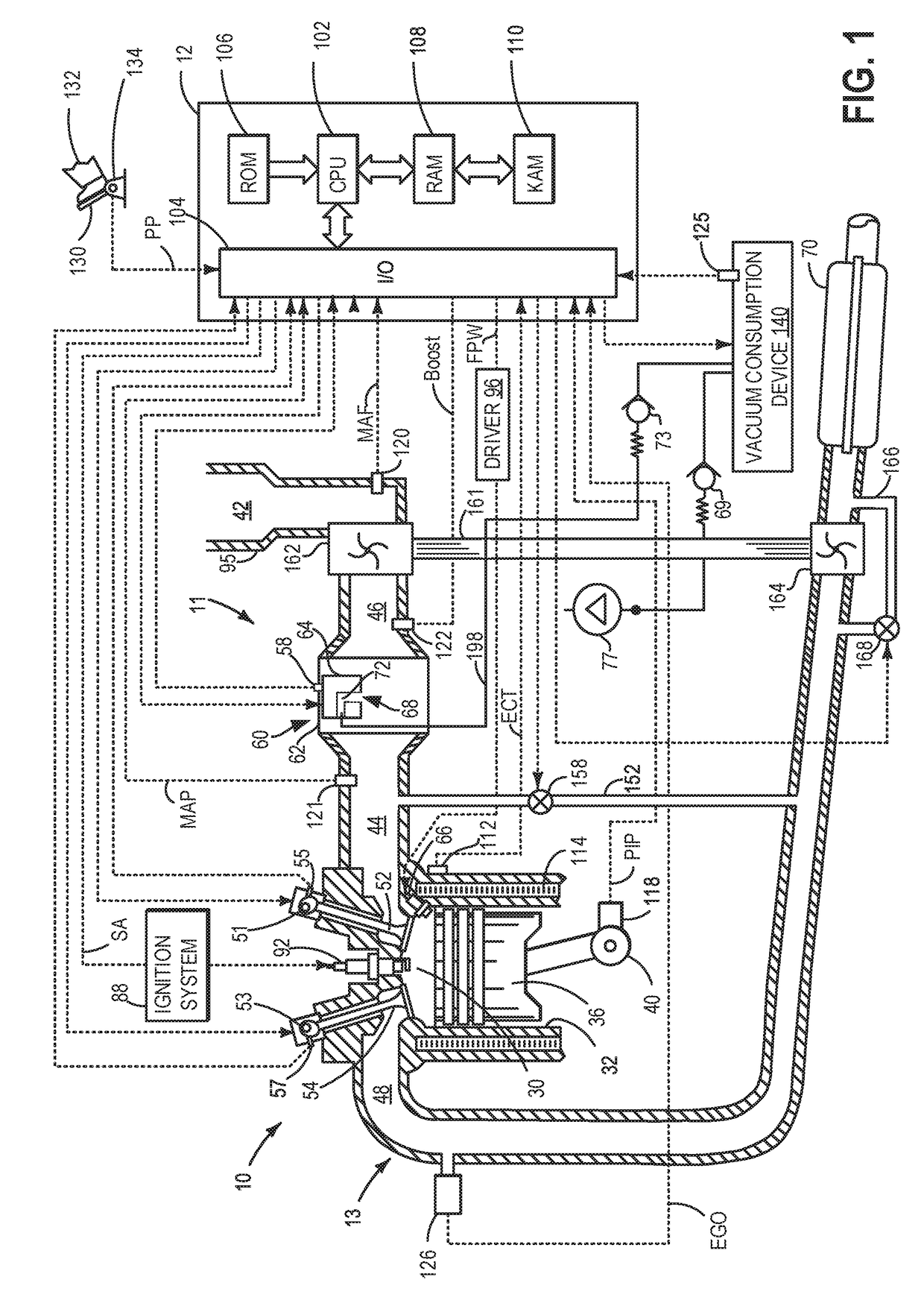
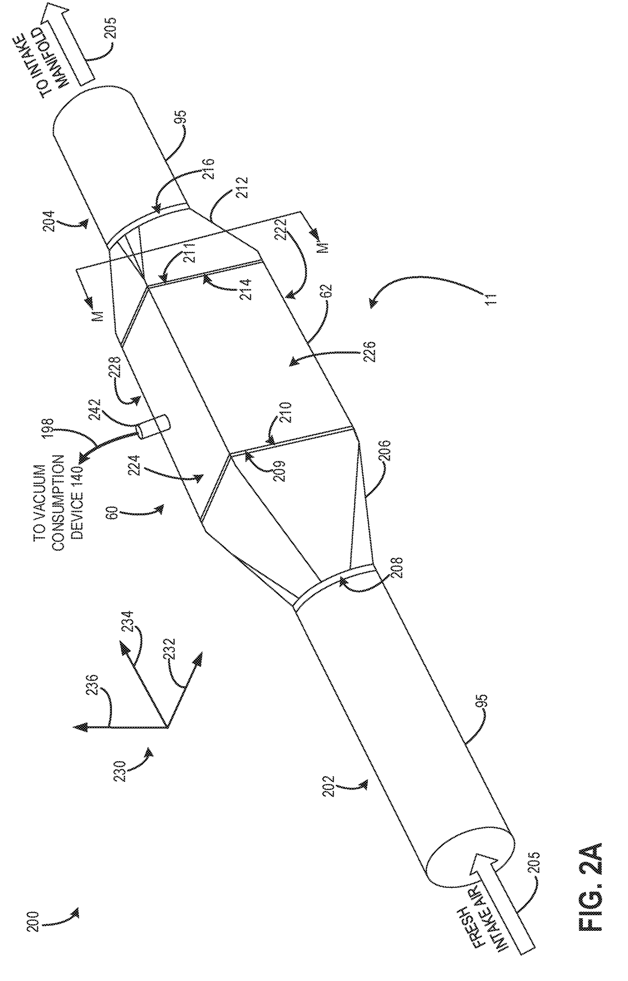
[0043]FIGS. 2A and 2B illustrate side perspective views of a portion of engine intake 11 of engine 10 of FIG. 1 that includes throttle 60. As such, components previously introduced in FIG. 1 are numbered similarly in FIGS. 2A and 2B and may not be reintroduced.

[0044]FIG. 2A shows an exterior side perspective view 200 of throttle 60 incorporated in intake conduit 95 within engine intake 11. FIG. 2B shows an interior side perspective view 250 of the throttle 60. Specifically, FIG. 2B shows the same side perspective view of throttle 60 shown in FIG. 2A, except that in FIG. 2B, the throttle 60 is illustrated as transparent, so as to expose the throttle valve 64 and interior of the throttle 60. FIGS. 2A and 2B may therefore be described together in the description herein.

[0045]In the description herein, axis system 230 may be used to describe the relative positioning of components of the throttle 60. The axis system 230 may comprise a vertical axis 236, a longitudinal axis 234, and a lat...

second embodiment

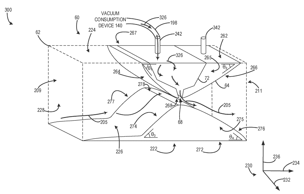
[0079]FIG. 3B shows an internal side perspective view 350 of the throttle 60. FIG. 3B is substantially similar to FIG. 3A, however, the hollow interior passage 72 and the opening 68 are located in with the flange 240. Specifically FIG. 3B shows the internal structure of the flange 240, including the hollow interior passage 72 located therein. Hollow interior passage 72 may fluidically couple the shaft 242 to the opening 68. As such, gasses from the vacuum consumption device 140 may flow into the interior passage 72 via the shaft 242, and may then exit the interior passage 72 and flange 240 via the opening 68. Interior passage 72 may define a volume of the flange 240. Portions of the flange 240 not including the interior passage 72 may not be hollow. Shaft 242 may extend into the interior of the passage 72 from outside the throttle body 62.

[0080]A front side surface 265 of the throttle valve 64 may be in sealing contact with the front side wall 226 of the throttle body 62. Further a ...

embodiment 400

[0091]FIG. 4A shows an embodiment 400, where throttle valve 64 is in the open first position. Airflow through the throttle body 62 may be greater with the throttle valve 64 in the open first position than any other throttle position. Thus, the position of the throttle valve 64 shown in FIG. 4A may be referred to as a fully open position. Throttle valve 64 may not overlap with the flange 240. More precisely, a given cross-section of the throttle body 62 taken along the vertical axis 236, may not include both the flange 240 and throttle valve 64, when the throttle valve is adjusted to the open first position. Said another way, no portion of the throttle valve 64 may be positioned over any portion of the flange 240. However, in other examples, some overlap between the throttle valve 64 and the flange 240 may exist in the open first position. As such, a narrowing of the throttle body 62 may be less in the open first position, than more closed positions, and airflow through the throttle ...


PUM


Abstract

Various systems and methods are described for generating vacuum within an engine intake. A system may comprise a throttle body with a slideable throttle body and a throttle fixture with a hollow interior passage located therein.

Description

CROSS REFERENCE TO RELATED APPLICATION[0001]The present application is a continuation-in-part of U.S. patent application Ser. No. 14 / 945,254, entitled “METHOD AND SYSTEM FOR VACUUM GENERATION USING A THROTTLE BODY COMPRISING A SLIDABLE THROTTLE VALVE,” filed on Nov. 18, 2015, the entire contents of which are hereby incorporated by reference for all purposes.TECHNICAL FIELD[0002]The present application relates to vacuum generation in an intake via a throttle valve.BACKGROUND AND SUMMARY[0003]Vehicle systems may include various vacuum consumption devices that are actuated using vacuum. These may include, for example, a brake booster and a purge canister. Vacuum used by these devices may be provided by a dedicated vacuum pump. In other embodiments, one or more aspirators (alternatively referred to as ejectors, venturi pumps, jet pumps, and eductors) may be coupled in the engine system that may harness engine airflow and use it to generate vacuum.[0004]In yet another example embodiment ...

Claims


Application Information

Patent Timeline
IPC IPC(8): F02D41/00F02M19/08F02M25/08F02D9/10
CPCF02D41/0002F02D9/104F02M25/0836F02M19/08F02D9/1055F02D9/14F02D2041/0017F02D2250/41F02M35/10222F02M35/10229Y02T10/40
Inventor ZHANG, XIAOGANG
Owner FORD GLOBAL TECH LLC
Why Eureka
Try Eureka