Device for measuring at least one physical quantity of an electric installation

a technology for measuring devices and electrical installations, applied in measurement devices, instruments, voltage/current isolation, etc., can solve problems such as difficult correction, wrong measurement values, and often source of installation configuration and check phas

Active Publication Date: 2017-05-18
SOCOMEC
View PDF0 Cites 24 Cited by
  • Summary
  • Abstract
  • Description
  • Claims
  • Application Information

AI Technical Summary

Problems solved by technology

When putting in place power measurement devices on an electrical installation, the installation configuration and check phase is often a source of errors, in particular in three-phase networks.
Consequently, the errors made in this installation phase are mainly due to wrong connection of the current measurement channels and of the voltage measurement channels between the sensors and the measuring units, to a wrongly declared sensor range, to a reversal of current sensor polarity, etc.
These errors can sometimes be difficult to correct and can even, in certain cases, remain unnoticed for some time, which can lead to wrong measurement values and consequently to incorrect decisions in the management of the electrical installation.
Conversely, the precision current sensors remain expensive, as they are based on costly and large magnetic materials.
However, this calibration data must be transmitted to the measuring device, otherwise the measured values will remain inaccurate.
This constraint involves a certain complexity of the current sensor, which necessarily leads to extra cost that is not always justified in view of the consider

Method used


Image

  • Device for measuring at least one physical quantity of an electric installation
  • Device for measuring at least one physical quantity of an electric installation
  • Device for measuring at least one physical quantity of an electric installation

Examples


first embodiment

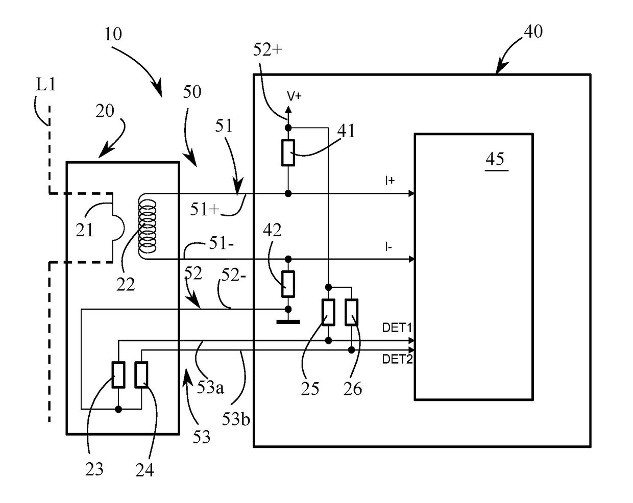
[0016]In a first embodiment variant, the measuring device can comprise at least one auxiliary voltage sensor arranged to measure an auxiliary voltage value representative of the voltage present on the conductor whose current is measured by said current sensor, this auxiliary voltage value forming an auxiliary physical quantity forwarded on one of the conductors of said communication pair.

[0017]This auxiliary voltage sensor can be incorporated in said current sensor or mounted serially between said current sensor and said measuring unit, and connected to each of them by means of at least one connection cable.

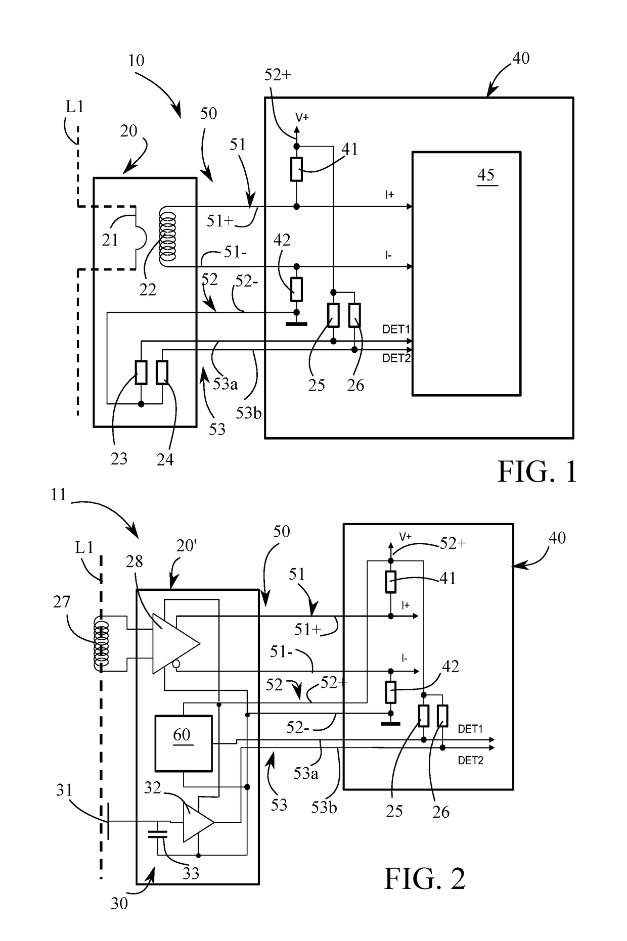
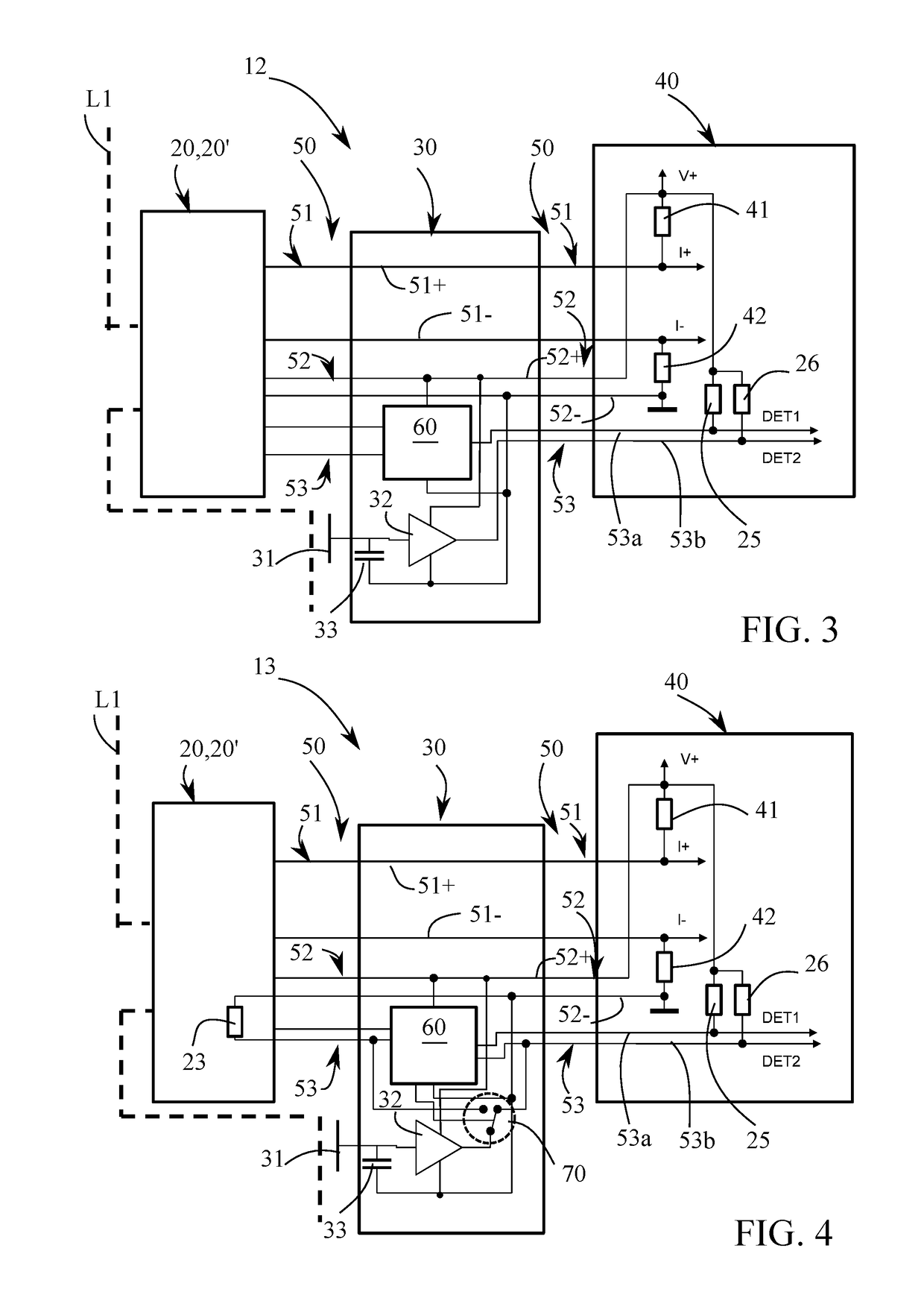
[0018]This auxiliary voltage sensor can comprise at least one selector arranged to automatically reverse the connection direction of said auxiliary voltage sensor between said current sensor and said measuring unit in case of a connection error.

second embodiment

[0019]In a second embodiment variant, the current sensor can comprise at least one earth leakage current sensor with a very low frequency in comparison with the frequency of the network powering said electrical installation, arranged to measure an earth leakage current value with a bandwidth including at least the frequency of the power supply network, this earth leakage current value forming an auxiliary physical quantity forwarded on one of the conductors of said communication pair.

third embodiment

[0020]In a third embodiment variant, the current sensor can comprise at least one temperature sensor arranged to measure the temperature of said current sensor, this temperature forming an auxiliary physical quantity forwarded on one of the conductors of said communication pair.


PUM


Abstract

A measuring device (10) comprising a current sensor (20) and a measuring unit (40) connected to each other by a connection cable (50). The connection cable (50) comprises three pairs of conductors of which a first measurement pair (51) is arranged to transmit a signal representative of the current measured by the sensor (20), a second power supply pair (52) is arranged to power electrically the sensor (20) and the measuring unit (40), and a third communication pair (53) is arranged to transmit at least one complementary signal between the sensor (20) and the measuring unit (40), such as an identification feature of the sensor allows the measuring unit to recognize automatically the sensor and provide an exploitable correlated value of the current measured by the sensor (20).

Description

TECHNICAL SCOPE[0001]This invention relates to a device for measuring at least one physical quantity of an electrical installation, comprising at least one sensor arranged to measure at least said physical quantity and provide at least one signal representative of said physical quantity, and at least one measuring unit arranged to receive said signal and process it to deliver at least one exploitable measurement value, said sensor and said measuring unit being connected to each other by means of at least one connection cable, said connection cable comprising at least three pairs of conductors, of which a first pair of conductors called measurement pair arranged to transmit said signal representative of said physical quantity measured by said sensor, a second pair of conductors called power supply pair arranged to electrically power said sensor through said measuring unit, and a third pair of conductors called communication pair arranged to transmit at least one complementary signal ...

Claims


Application Information

Patent Timeline
IPC IPC(8): G01R15/18G01R31/04
CPCG01R15/18G01R15/181G01R31/041G01D21/02G01R19/00G01R31/00G01D3/022G01R31/67
Inventor KERN, CHRISTIAN
Owner SOCOMEC
Why Eureka
Try Eureka