Backlight unit of high light coupling efficiency

a backlight unit and high light coupling technology, applied in the field of display, can solve the problems of poor heat dissipation effect of a conventional light-emitting diode, the inability to remove the limits of low brightness of a single lamp, and the relatively low transmittance of a large-sized high-definition lcd panel, so as to achieve the effect of dissipating heat generated

Active Publication Date: 2017-05-18
TCL CHINA STAR OPTOELECTRONICS TECH CO LTD
View PDF2 Cites 0 Cited by
  • Summary
  • Abstract
  • Description
  • Claims
  • Application Information

AI Technical Summary

Benefits of technology

[0015]The backlight unit of the present disclosure is provided with edge type light source components beside two neighboring side walls of the light guide plate, and a heat dissipation element for dissipating heat of the edge type light source components, which may effectively dissipate heat generated during the operation of the light source components, thereby avoiding the mura phenomenon caused by a change of a light coupling distance due to the expansion of the light guide plate because of overheating. Meanwhile, space retainers are disposed between the light guide plate and the respective light source components, which may effectively prevent the light guide plate from being expanded due to overheating to crack up the LED.

Problems solved by technology

As for an edge type LCD panel, if it merely adopts unilateral incident light, it cannot get rid of limits of low brightness of a single lamp and poor heat dissipation effect of a conventional Light-Emitting Diode (LED).
Plus, transmittance of a large-sized high definition LCD panel is relatively low, thus, a designed brightness of a single long side cannot achieve a set brightness.
However, the light guide plate having this structure cannot dissipate heat uniformly, which is easily heated and expanded due to moisture absorption to cause mura (i.e., various shadow phenomenon caused by nonuniform brightness of a display).
Meanwhile, the light guide plate may also crack up the LED due to the expansion.
However, due to the increase of the light coupling distance, a light coupling efficiency of the light incident into the light guide plate is greatly decreased, especially, in the types of the devices that require for a narrow bezel design, in order to avoid edge light leakage, it is generally to add a material with low reflectivity over a light coupling region to reduce a risk of light leakage, so that the light coupling efficiency is further reduced.

Method used


Image

  • Backlight unit of high light coupling efficiency
  • Backlight unit of high light coupling efficiency

Examples


embodiment 1

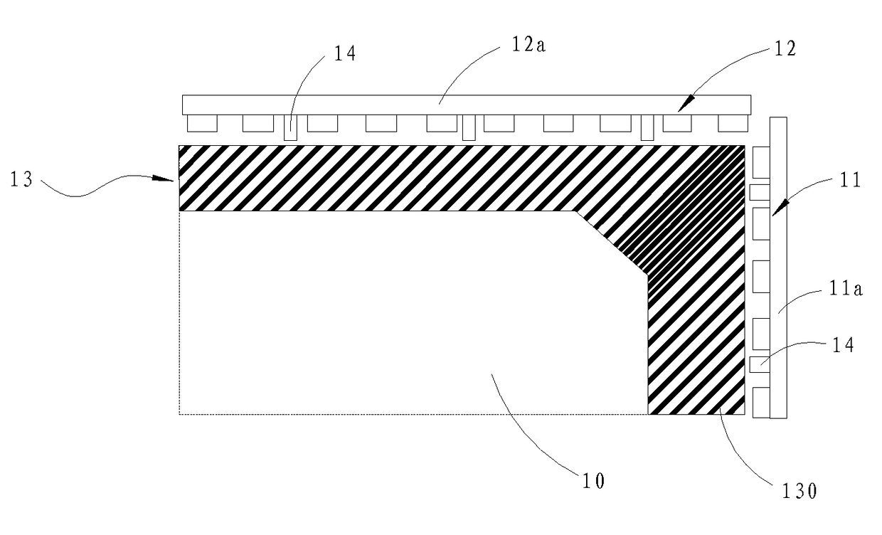
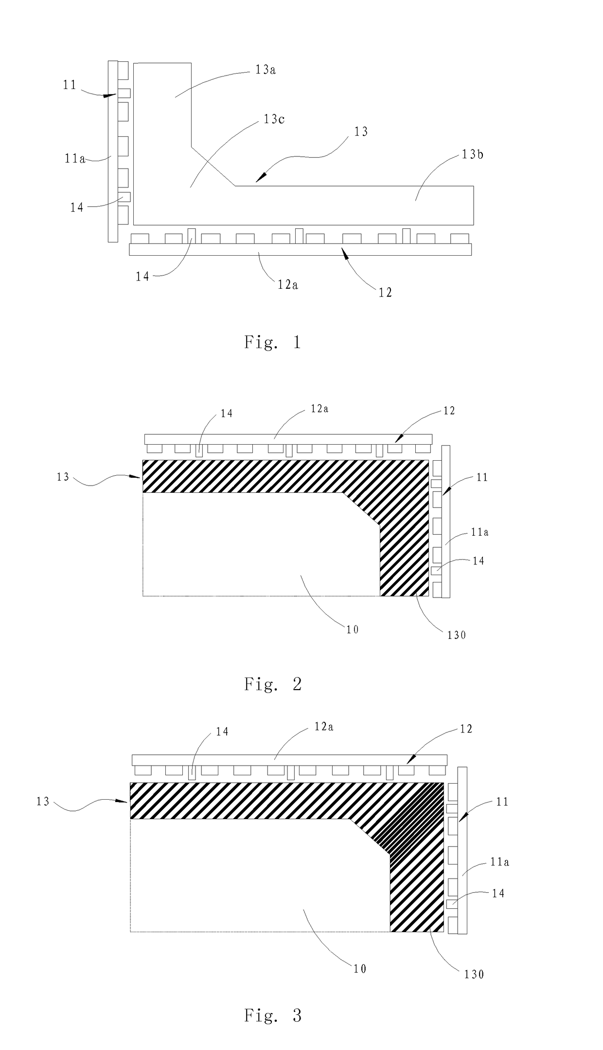
[0020]By referring to FIGS. 1 and 2, the present disclosure provides a backlight unit of high light coupling efficiency including a light guide plate 10, a first light source component 11, a second light source component 12, and a heat dissipation element 13. The first and second light source components 11 and 12 are respectively disposed beside two neighboring side walls of the light guide plate 10, and each of the first and second light source components 11 and 12 consists of a substrate and LED lamp beads. The heat dissipation element 13 is a plate-like structure, contacts a first substrate 11a of the first light source component 11 and a second substrate 12a of the second light source component 12 simultaneously, and is disposed on a bottom of the light guide plate 10, for conducting heat generated during the operations of the first and second light source components 11 and 12 simultaneously, thereby preventing the LED lamp beads from being overheated to be damaged and reducing ...

embodiment 2

[0024]As shown in FIG. 3, it is different from Embodiment 1 that the heat dissipation grooves 130 of the present embodiment are set to have greatest density in the third portion 13c of the heat dissipation element 13, so that the respective portions may have the same heating conditions and temperatures of the LED lamp beads at different portions may be approximate to each other, which is beneficial to improve a service life of the backlight and enhance uniformity of the backlight brightness after a long-term use of a display device.

[0025]It should be understood that in other embodiments, heat dissipation fins etc. may be added to the back of the third portion 13c of the heat dissipation element 13 to resolve the problem of concentrate heat dissipation at this portion.

[0026]The backlight unit of the present disclosure is provided with edge type light source components beside two neighboring side walls of the light guide plate, and provided with a heat dissipation element for dissipat...


PUM


Abstract

A backlight unit of high light coupling efficiency including a light guide plate, a first light source component and a second light source component disposed beside two neighboring side walls of the light guide plate, and a heat dissipation element that contacts a first substrate of the first light source component and a second substrate of the second light source component simultaneously and is disposed on a bottom of the light guide plate. The backlight unit of the present disclosure can effectively dissipate heat generated during the operation of the light source components, thereby avoiding the mura phenomenon caused by a change of a light coupling distance due to the expansion of the light guide plate because of overheating.

Description

BACKGROUND OF THE INVENTION[0001]1. Field of the Invention[0002]The present disclosure relates to display technical field, and in particular, to a backlight unit of high light coupling efficiency.[0003]2. The Related Arts[0004]As a development of liquid crystal televisions (TVs) is tended to large size and high-definition 4K even 8K resolution technique, the number of pixel units of a liquid crystal display (LCD) panel is increased, the size and the aperture ratio of a pixel are decreased, and the transmittance of a LCD panel is also reduced.[0005]In order to improve transmittance of a large-sized LCD panel, it needs to enhance backlight brightness. As for an edge type LCD panel, if it merely adopts unilateral incident light, it cannot get rid of limits of low brightness of a single lamp and poor heat dissipation effect of a conventional Light-Emitting Diode (LED). Plus, transmittance of a large-sized high definition LCD panel is relatively low, thus, a designed brightness of a sing...

Claims


Application Information

Patent Timeline
Patent Type & Authority Applications(United States)
IPC IPC(8): F21V8/00
CPCG02B6/0068G02B6/0085F21S8/00G02B6/0091
Inventor FAN, YONG
Owner TCL CHINA STAR OPTOELECTRONICS TECH CO LTD
Why Eureka
Try Eureka