
Relay Selection Routing Method and Relay Selection Routing Apparatus Based on Direct Communication of Terminal

a relay selection and routing method technology, applied in the field of terminals, can solve the problems of poor quality of link c-to-b, inability to establish direct communication, and no centralized control node, so as to avoid the massive signaling overhead caused by flooding routing in the existing routing algorithm, avoid unnecessary signaling overhead, and smooth data sharing

Active Publication Date: 2017-05-18
NANCHANG COOLPAD INTELLIGENT TECH CO LTD
View PDF3 Cites 16 Cited by
  • Summary
  • Abstract
  • Description
  • Claims
  • Application Information

AI Technical Summary

Benefits of technology

The present invention provides a new way to solve problems in existing routing algorithms. This solution can reduce the amount of signaling needed and improve the speed of a database. It can also make it more efficient to establish a relationship between different parts of a network without sending unnecessary signals.

Problems solved by technology

In these current routing algorithms, the routing problem of a distributed system is usually processed, that is, there is no centralized control node between routers to uniformly maintain and process the routing tables.
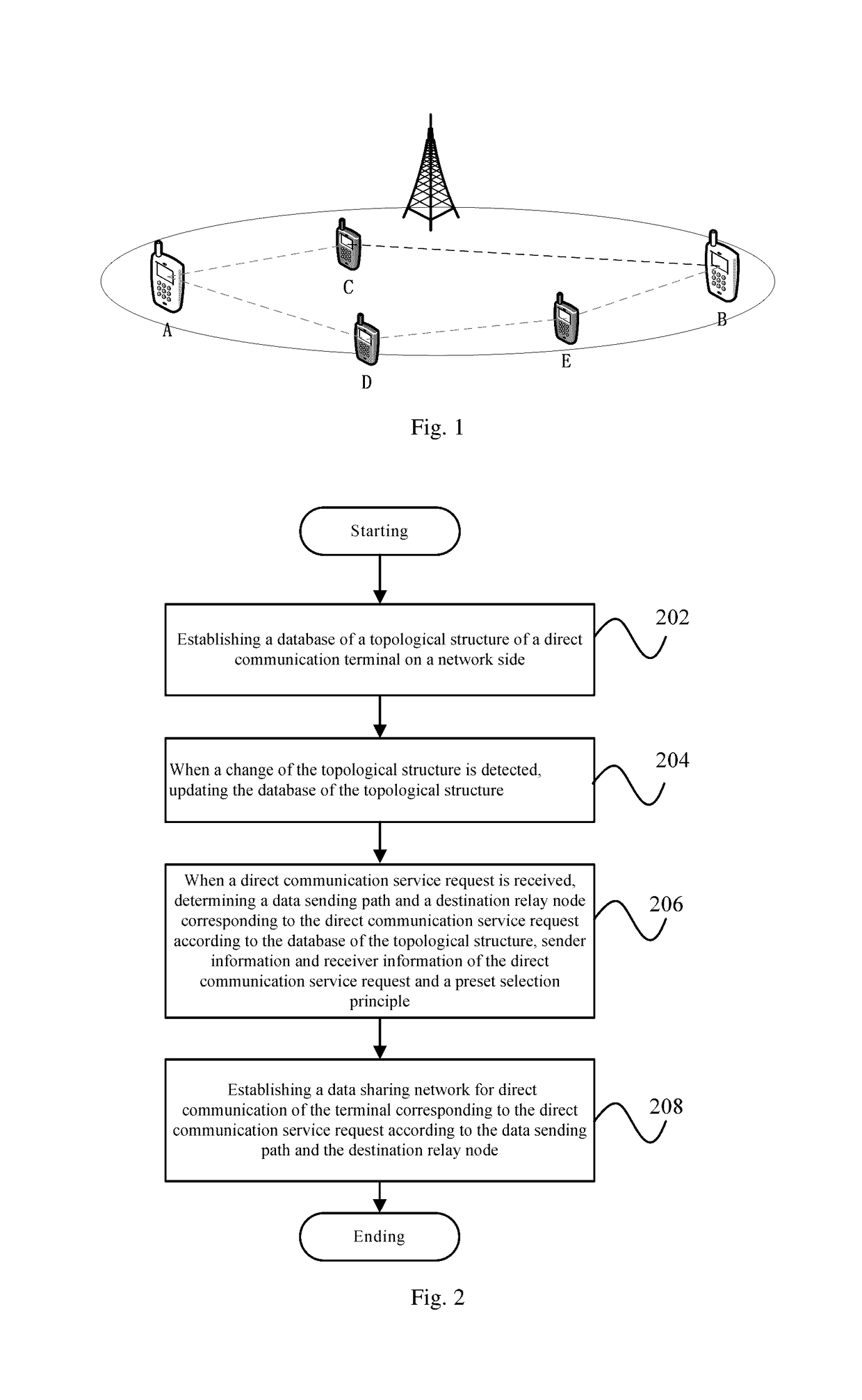
It can be seen from FIG. 1 that, according to a channel detection result, a link C-to-B has worse quality, and thus cannot establish direct communication.
No matter which aforementioned routing algorithm is adopted, due to massive invalid broadcasts generated during the routing discovery broadcast process, a larger signaling cost burden will be caused.
Moreover, the process is unlikely to converge, and thus a larger delay will be generated in the entire process of path selection.

Method used


Image

  • Relay Selection Routing Method and Relay Selection Routing Apparatus Based on Direct Communication of Terminal
  • Relay Selection Routing Method and Relay Selection Routing Apparatus Based on Direct Communication of Terminal
  • Relay Selection Routing Method and Relay Selection Routing Apparatus Based on Direct Communication of Terminal

Examples


Embodiment Construction

[0091]In order that the aforementioned purposes, features and advantages of the present invention can be understood more clearly, a further detailed description of the present invention will be given below in combination with accompanying drawings and specific implementations. It should be noted that embodiments in the present application and the features in the embodiments can be combined with each other as long as no conflict is generated.

[0092]A lot of specific details are described in the description below to fully understand the present invention, but the present invention can also be implemented in other manners different from what is described herein, therefore the protection scope of the present invention is not limited to the specific embodiments disclosed below.

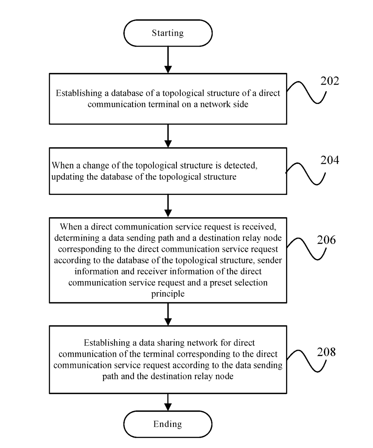
[0093]FIG. 2 shows a flowchart of a relay selection routing method according to an embodiment of the present invention.

[0094]As shown in FIG. 2, the relay selection routing method according to the embodiment of the ...


PUM


Abstract

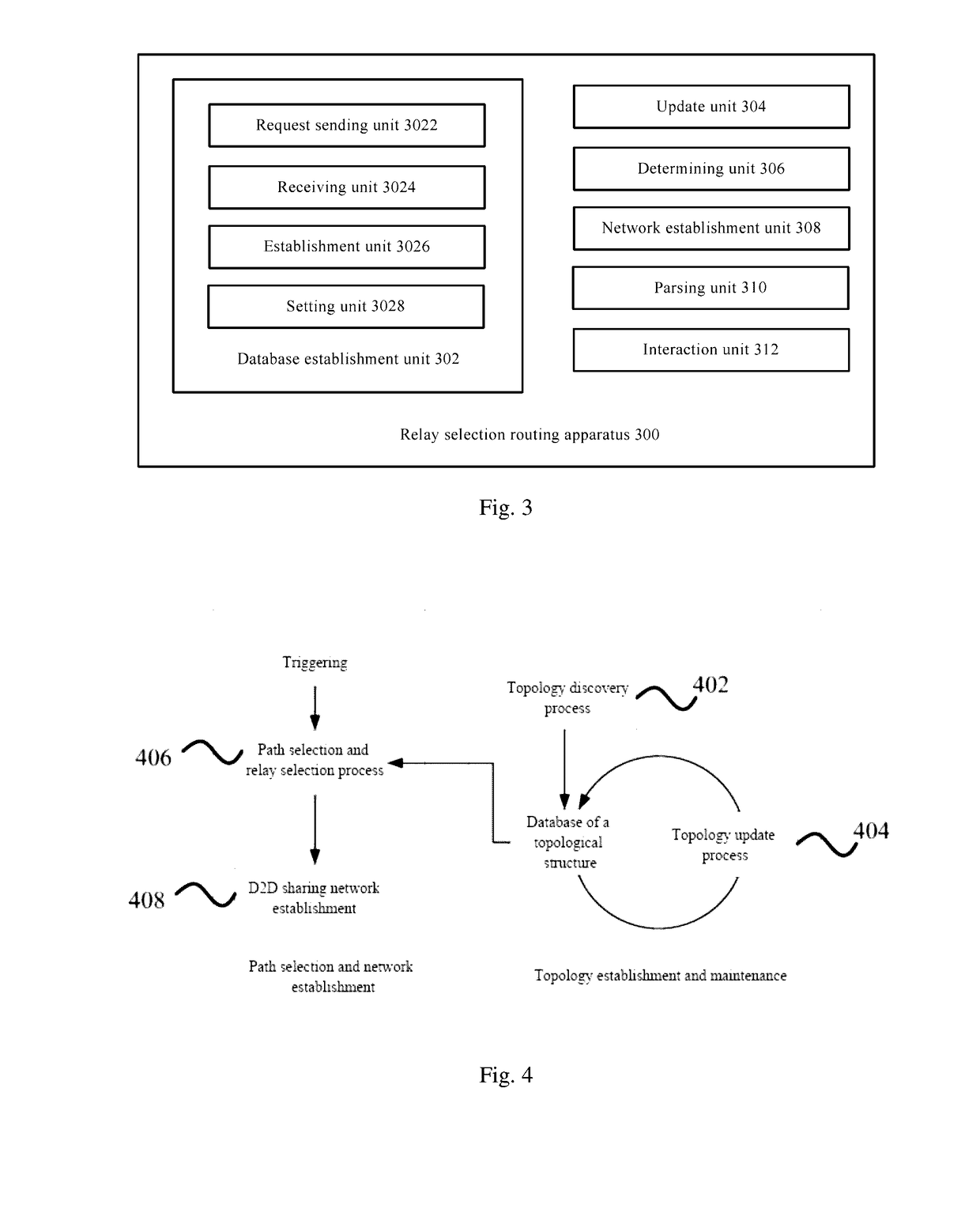
The present invention provides a relay selection routing method based on direct communication of a terminal, applied to a base station, including: establishing a database of a topological structure of a direct communication terminal on a network side; when a change of the topological structure is detected, updating the database of the topological structure; when a direct communication service request is received, determining a data sending path and a destination relay node corresponding to the direct communication service request according to the database of the topological structure, sender information and receiver information of the direct communication service request and a preset selection principle; and establishing a direct communication data sharing network corresponding to the direct communication service request according to the data sending path and the destination relay node. Correspondingly, the present invention further provides a relay selection router based on direct communication of a terminal.

Description

FIELD OF THE INVENTION[0001]The present invention relates to the technical field of terminals, and particularly to a relay selection routing method based on direct communication of a terminal and a relay selection routing apparatus based on the direct communication of the terminal.BACKGROUND OF THE INVENTION[0002]Routing algorithms are the core technology of an Internet network layer, which mainly solves the problem of how to select an appropriate path and an appropriate router to forward data in an IP network. The current routing algorithms are divided into an active routing algorithm (a table-driven routing protocol) and on-demand routing (a reactive routing protocol).[0003]Active routing protocol: an active routing discovery strategy is similar to the traditional routing protocol, that is, each node of the network should periodically send the latest routing information to other nodes, and each node should maintain one or more routing tables to store the routing information. When ...

Claims


Application Information

Patent Timeline
IPC IPC(8): H04W16/14H04W8/00H04W4/00H04L45/02H04L45/42H04W4/70H04W76/14
CPCH04W16/14H04W84/18H04W8/005H04W4/005H04W40/12H04W40/246H04W40/248H04W40/30H04L45/02H04L45/26H04L45/42H04W76/14H04W88/04H04W4/70
Inventor ZHANG, CHENLU
Owner NANCHANG COOLPAD INTELLIGENT TECH CO LTD
Learn More