Shielded conduction path

a shielded and conduction path technology, applied in the direction of insulated conductors, cables, conductors, etc., can solve the problems of difficult routing of single-core electric wires at locations, higher stiffness of electric wires, and more difficult bends, so as to reduce the cross section of shielded conduction paths

Active Publication Date: 2017-05-25
SUMITOMO WIRING SYST LTD
View PDF6 Cites 7 Cited by
  • Summary
  • Abstract
  • Description
  • Claims
  • Application Information

AI Technical Summary

Benefits of technology

[0006]The present design was made in view of the above-described circumstances, and it is an object thereof to provide a shielded conduction path whose cross section can be reduced and which can be routed even at a location where flexibility is required.
[0007]A shielded conduction path according to the present design includes an electric wire and a shielding member configured to electromagnetically shield the electric wire by enclosing an outer circumference of the electric wire, wherein a core wire of the electric wire has a single-core portion which is formed by applying pressure to a predetermined portion of a conductor obtained by twisting a plurality of strands together and whose cross section has been reduced as a result of the application of the pressure causing the strands to be brought forcefully into intimate contact with each other and form a single body, and a stranded wire portion in which the plurality of strands remain in a twisted-together state with no pressure having been applied thereto, the shielding member has a first shielding portion enclosing a portion of the electric wire where the core wire constitutes the single-core portion and a second shielding portion enclosing a portion of the electric wire where the core wire constitutes the stranded wire portion, and the second shielding portion has higher flexibility than the first shielding portion.
[0008]With the shielded conduction path according to the present design, the inner diameter of the first shielding portion, which encloses a portion of the electric wire where the core wire constitutes the single-core portion, can be reduced in accordance with the cross-sectional size of a single-core wire, and the second shielding portion, which encloses a portion of the electric wire where the core wire constitutes the stranded wire portion, can be disposed at a location where flexibility is required. Thus, the cross section of the shielded conduction path can be reduced, and also the shielded conduction path can be routed even at a location where flexibility is required.

Problems solved by technology

However, the single-core electric wire has higher stiffness and hence is more difficult to bend than the stranded electric wire.
Thus, there is a problem in that it is difficult to route the single-core electric wire at locations, such as a location around a device, where flexibility is required.

Method used


Image

  • Shielded conduction path
  • Shielded conduction path
  • Shielded conduction path

Examples


embodiment

[0015]Hereinafter, an embodiment will be described in detail with reference to FIGS. 1 to 3.

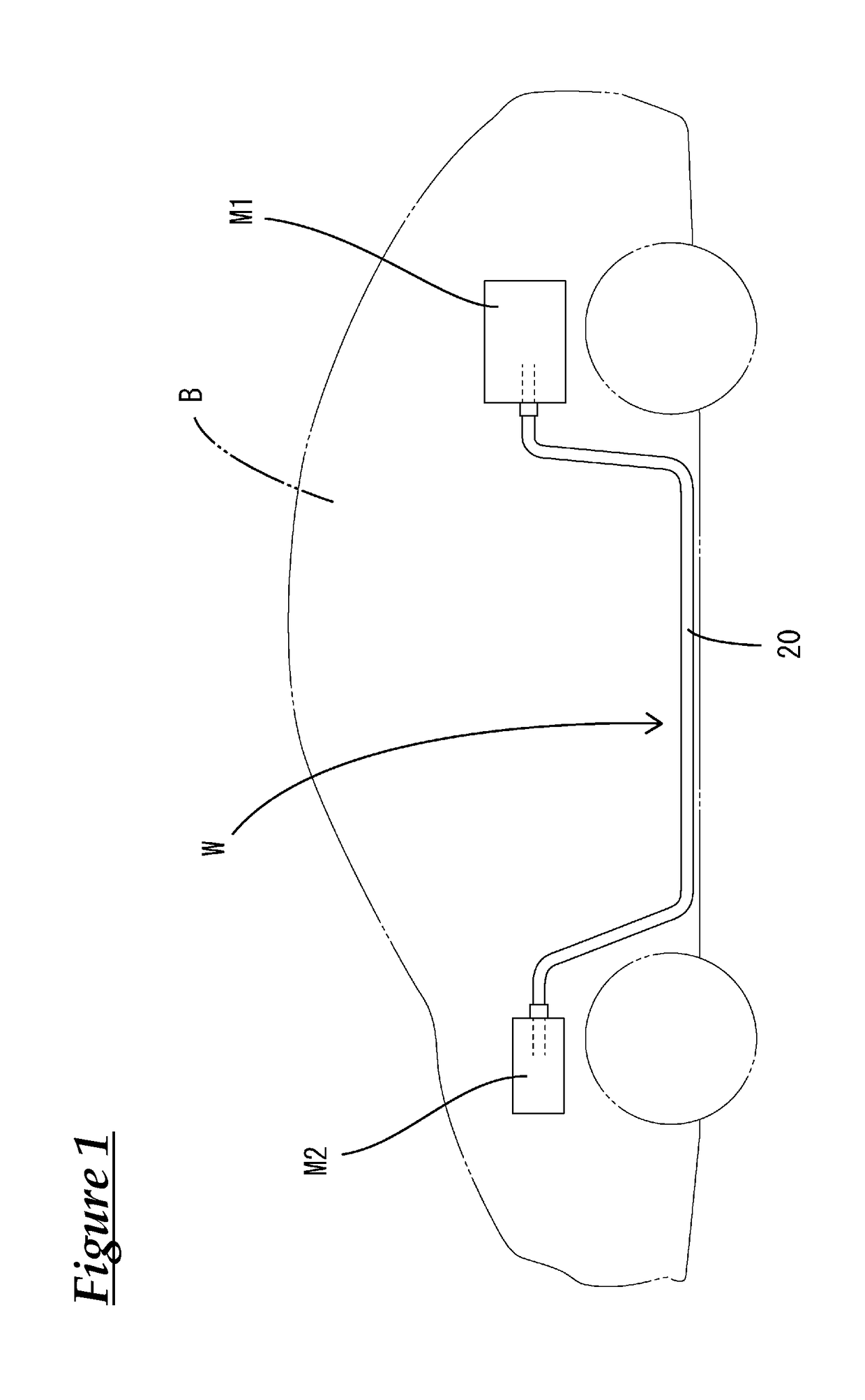
[0016]As shown in FIG. 1, a shielded conduction path W according to the present embodiment is routed under a floor of a vehicle B, such as a hybrid vehicle, in order to connect, for example, a device Ml, such as a high-voltage battery, that is provided in a rear portion of the vehicle B to a device M2, such as an inverter or a fuse box, that is provided in a front portion of the vehicle B. The devices M1 and M2 are accommodated in conductive shielding cases, respectively.

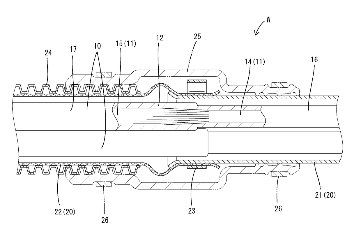
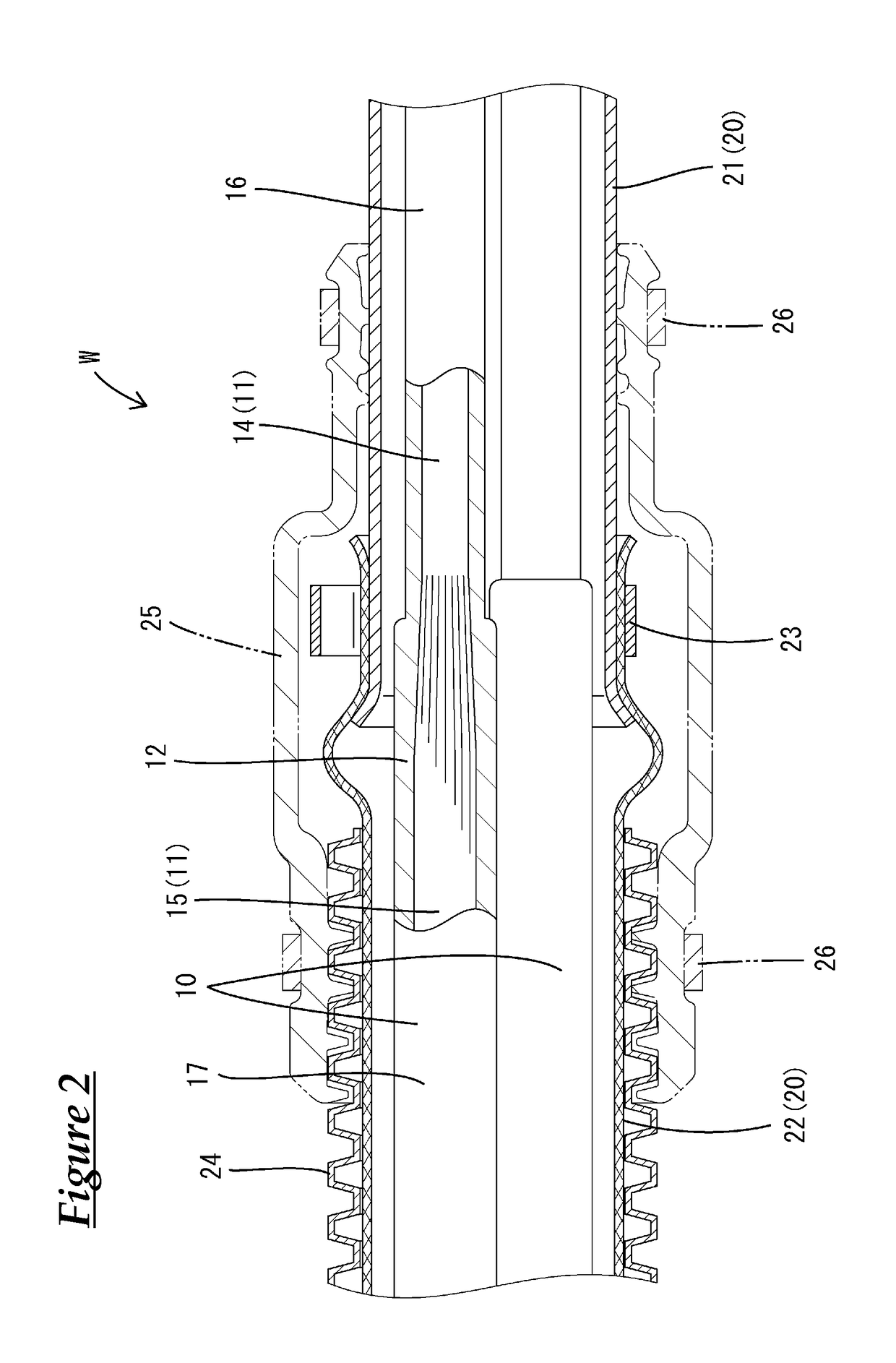
[0017]In the shielded conduction path W of the present embodiment, a plurality of (two, in the present embodiment) electric wires 10 are collectively enclosed and electromagnetically shielded by a shielding member 20.

[0018]Each electric wire 10 is a non-shielded electric wire obtained by enclosing an outer circumference of a core wire 11 formed of copper, a copper alloy, aluminum, or an aluminum alloy with an insulating coati...


PUM

PropertyMeasurementUnit
shielded conductionaaaaaaaaaa
outer circumferenceaaaaaaaaaa
pressureaaaaaaaaaa

Abstract

An electric wire and a shielding member configured to electrically shield the electric wire by enclosing an outer circumference thereof. A core wire of the electric wire has a single-core portion which is formed by applying pressure to a portion of a conductor obtained by twisting a plurality of strands together to reduce their cross section. This causes the strands to be brought into intimate contact with each other and form a single body, and a stranded wire portion in which the strands remain in a twisted-together state with no pressure having been applied thereto. The shielding member has a first shielding portion enclosing a portion of the electric wire where the core wire constitutes the single-core portion, and a second shielding portion enclosing a portion of the electric wire where the core wire constitutes the stranded wire portion. The second shielding portion has higher flexibility than the first shielding portion.

Description

CROSS REFERENCE TO RELATED APPLICATIONS[0001]This application claims the priority of Japanese patent application JP2014-28022 filed on Jun. 23, 2014, the entire contents of which are incorporated herein.TECHNICAL FIELD[0002]The present invention relates to a shielded conduction path in which an electric wire is enclosed by a shielding member.BACKGROUND ART[0003]Conventionally, in vehicles such as hybrid automobiles, there are cases where a plurality of electric wires are routed under the floor of a vehicle in order to connect, for example, devices, such as a high-voltage battery, provided in a rear portion of the vehicle to devices, such as an inverter and a fuse box, provided in a front portion of the vehicle. A shielded conduction path for use in such cases is known which is configured to block noise by enclosing an outer circumference of the electric wires with a shielding member.[0004]For example, a shielded conduction path disclosed in Patent Document 1 (JP 2011-173456A) noted ...

Claims


Application Information

Patent Timeline
Patent Type & Authority Applications(United States)
IPC IPC(8): H01B7/17H01B7/00
CPCH01B7/0009H01B7/17H05K9/0098H02G3/0468H02G3/0481H02G3/06B60R16/0215
Inventor NAKAI, HIROKAZU
Owner SUMITOMO WIRING SYST LTD
Why Eureka
Try Eureka