Integrated antenna unit hook, hang eject-inject installation system

a technology of integrated antenna units and installation systems, applied in the direction of collapsible antennas, antenna details, antennas, etc., can solve the problems that current systems do not provide a way to perform these functions, and achieve the effect of convenient and safe suppor

Active Publication Date: 2017-05-25
AMPHENOL ANTENNA SOLUTIONS
View PDF3 Cites 11 Cited by
  • Summary
  • Abstract
  • Description
  • Claims
  • Application Information

AI Technical Summary

Benefits of technology

[0007]Therefore a need exists for antenna systems to have mechanisms that conveniently and safely support installation and removal of antenna related devices while installed on the tower / structure. The present invention permits remote radio units or similar devices to be safely temporarily hung or suspended onto an antenna. This allows the service provider to attach cables / connectors (such as Common Public Radio Interface (CPRI) cables / connectors) to remote radio units or similar components prior to final installation while on tower / structure.
[0008]Accordingly, it is an object of the invention to provide an antenna system that can be easily serviced and replaced while installed on a tower or other structure. It is a further object of the invention to provide an antenna system in which an RRU can be easily removed and replaced from an IAU.
[0009]In accordance with these and other objectives, the invention is an antenna unit system, such as an IAU, that connects with a radio unit, such as an RRU. The IAU has a docking station that receives the RRU. A mechanical tab is attached to remote radio unit or similar device which into back of antenna body, permitting RRU to hang / suspend above the docking station prior to full installation. This creates clearance and visibility to allow the installer to attach CPRI cable and connectors before the RRU is fully engaged with docking station on the IAU. A mechanical handle(s) is attached to the RRU that assists lowering RRU into docking station and further injecting / compressing the RRU into the docking station. When removing the RRU from the docking station, pressing the handle(s) upwards assists in ejecting / removing the RRU from the docking station through a cam and follower configuration.
[0010]Multiple eyelets are included in the antenna docking station and mounting hardware to provide anchor points to attach carabiners or equivalent clamping with tensile wire with features which can be tethered to the RRU or related devices. That provides protection from falling or means to manipulate the antenna system while installing or removal.

Problems solved by technology

Current systems do not provide a way to perform these functions while installed in the raised position.

Method used


Image

  • Integrated antenna unit hook, hang eject-inject installation system
  • Integrated antenna unit hook, hang eject-inject installation system
  • Integrated antenna unit hook, hang eject-inject installation system

Examples


Embodiment Construction

[0024]In describing a preferred embodiment of the invention illustrated in the drawings, specific terminology will be resorted to for the sake of clarity. However, the invention is not intended to be limited to the specific terms so selected, and it is to be understood that each specific term includes all technical equivalents that operate in similar manner to accomplish a similar purpose. Several preferred embodiments of the invention are described for illustrative purposes, it being understood that the invention may be embodied in other forms not specifically shown in the drawings.

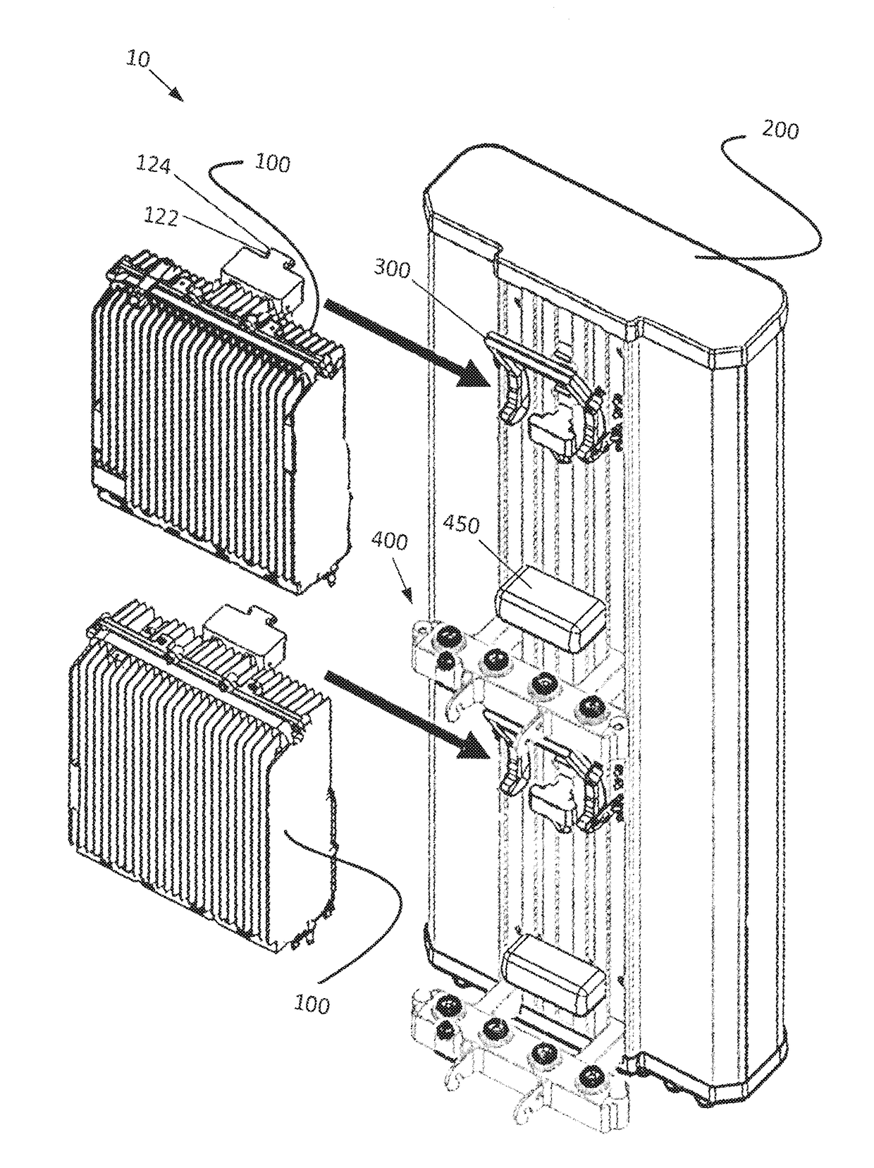
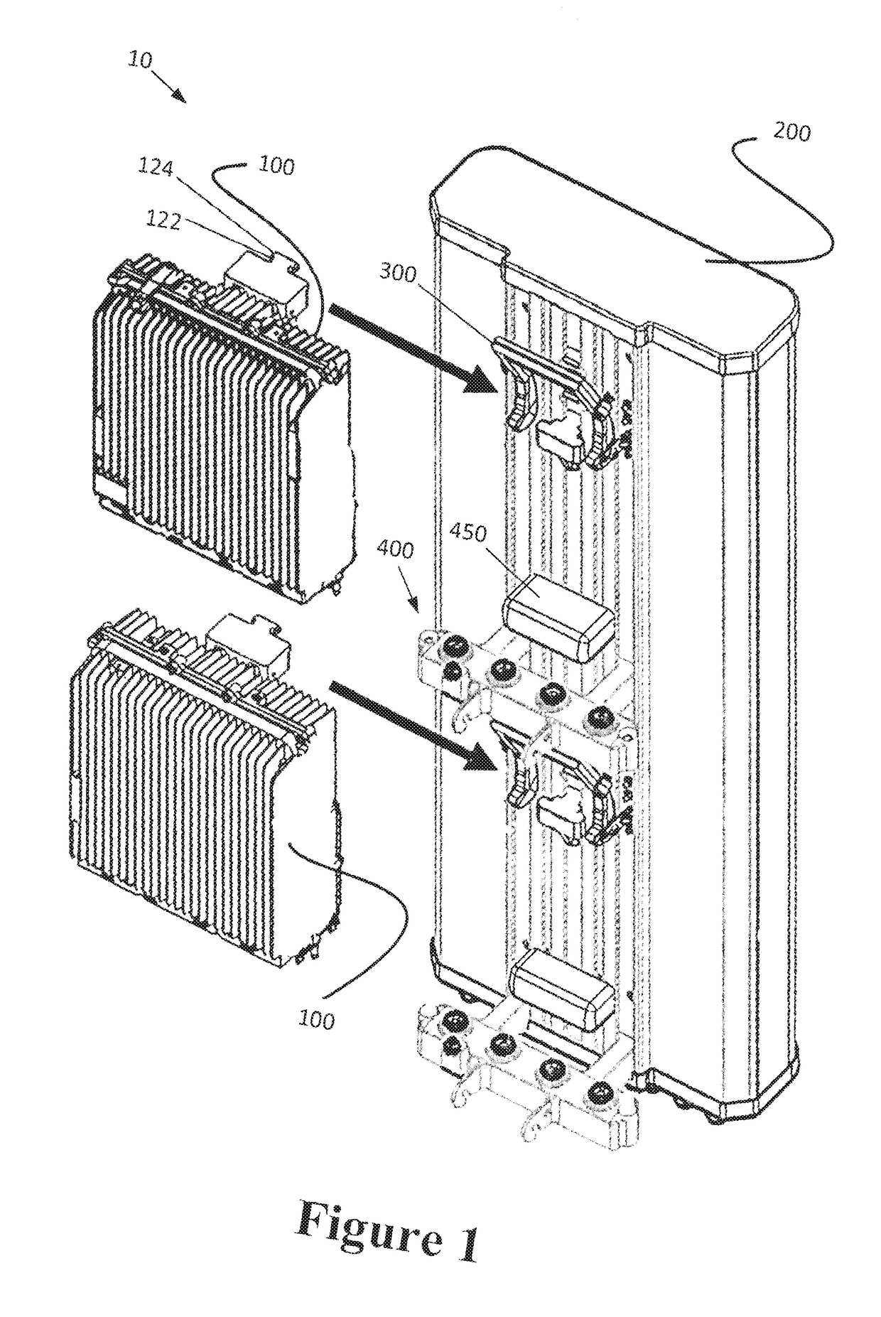
[0025]Turning to the drawings, FIG. 1 shows the antenna system comprising an integrated antenna unit 10 in accordance with an illustrative, non-limiting embodiment of the invention. The antenna system 10 includes an electronic component 100 (an RRU in the illustrated embodiment), an antenna structure or antenna 200, a quick release assembly 300, and a docking station 400. As shown in FIGS. 1, 2, the quic...


PUM


Abstract

An antenna system having a quick release that removably and reliably connects a Remote Radio Unit (RRU) to an Integrated Antenna Unit (IAU), both mechanically and electronically. The RRU has an RRU connector and the antenna has an antenna connector that removably engages with and mates with the RRU connector. The system has a temporary hanging position that enables a user to connect additional electronic connections to the RRU before it is fully coupled with the antenna.

Description

RELATED APPLICATIONS[0001]This application claims the benefit of U.S. Provisional Application No. 62 / 259,963, filed Nov. 25, 2015, the entire contents of which are incorporated herein by reference.BACKGROUND OF THE INVENTION[0002]Field of the Invention[0003]The invention relates to mechanical functions of antenna systems. More specifically, the invention relates to mechanical features used on integrated antenna units which aid in installation and removal of remote radio units or similar components attached to antennas.[0004]Background of the Related Art[0005]Currently, wireless service providers assemble antenna systems, such as an Integrated Antenna Unit (IAU), at ground level. That assembly includes attaching Remote Radio Units (RRU) and associated hardware to a pole or structure, which requires connecting cable assemblies and associated components at ground level. Once the system is raised and installed on tower / structure, any changes that may be needed, such as servicing and / or ...

Claims


Application Information

Patent Timeline
Patent Type & Authority Applications(United States)
IPC IPC(8): H01Q1/12H01Q1/24H01Q1/42H01Q1/20
CPCH01Q1/1228H01Q1/42H01Q1/246H01Q1/20H01Q1/088H01Q1/1207
Inventor SIERZENGA, JEFFREYHO, JIMMYTANG, CHENGCHENGBERRY, ERIC BRIANLIU, JEFFERY JIERIEK, JUSTIN
Owner AMPHENOL ANTENNA SOLUTIONS
Why Eureka
Try Eureka