Method and device for calibrating post-injections of an internal combustion engine

a post-injection and internal combustion engine technology, which is applied in the direction of combustion engines, machines/engines, electric control, etc., can solve the problems of low temperature of particle filters, damage to filter components, and inability to provide post-injections that are not instantaneously effective and relatively late in terms of time, and achieves a relatively simple and cost-effective

Inactive Publication Date: 2017-06-01
ROBERT BOSCH GMBH
View PDF7 Cites 5 Cited by
  • Summary
  • Abstract
  • Description
  • Claims
  • Application Information

AI Technical Summary

Benefits of technology

[0011]This is based on the experimentally demonstrated effect that the mentioned pressure drop for a late post-injection is generally proportional to the particular injection quantity within a relatively wide pressure range of approximately 200 bar to approximately 2000 bar, and the measured pressure drop therefore allows unequivocal conclusions to be drawn concerning the quantity of fuel that is injected during the post-injection.
[0012]The method provided according to the present invention may be implemented in a technically relatively simple, and therefore cost-effective, manner, and also provides a robust correction or calibration method for post-injections discussed here. In particular, no additional sensor system is necessary, since, with injection systems discussed here (common rail systems, for example), the method may be carried out using customary pressure sensors.
[0018]It is to be noted that the mentioned method steps, in particular the pressure measurement(s) and evaluation(s) or correction(s), do not have to be carried out in chronological succession or as a single unit, since intermediate results or values already present in a control unit are evaluated as soon as a correction value is present for at least one operating point, and this correction value is also used generally immediately. This has the advantage that correction values do not have to be present for all operating points. Alternatively, the evaluation does not take place until all data necessary for a final evaluation are present. In particular, in this case cylinder-individual reference values or control variables may be stored in corresponding characteristic maps, so that they are also available for subsequent evaluations.
[0020]The computer program according to the present invention is configured for carrying out each step of the method, in particular when it runs on a computer or a control unit. The computer program allows the method according to the present invention to be implemented on an electronic control unit without having to make structural changes to same. The machine-readable data medium on which the computer program according to the present invention is stored is provided for this purpose. By running the computer program according to the present invention on an electronic control unit, the electronic control unit according to the present invention is obtained, which is configured for controlling post-injections of an injection system discussed here with the aid of the method according to the present invention.

Problems solved by technology

In addition, for a fuel injection system discussed here, conventionally, post-injections are provided which are not instantaneously effective and are relatively late in terms of time, which react at the particle filter.
Examples of possible negative effects of an incorrectly metered post-injection include recirculation of uncombusted fuel, via the EGR, into an intake manifold of the internal combustion engine, an excessive temperature during the combustion in the particle filter due to a post-injection quantity that is too high, resulting in damage to filter components, and an excessively low temperature of the particle filter due to a post-injection quantity that is too low, so that regeneration is not possible.
One disadvantage of this procedure is that the concurrent correction of all partial injections may result in impermissible deviations of individual partial injections, and a mentioned temperature controller must be configured for each individual engine.
However, it has been shown that a transfer of the ZFC learned values from pre-injections to late post-injections is possible only to a very limited extent, since the exhaust gas back-pressures differ greatly for various crank angle positions of the start of injection.
An appropriately carried out back-pressure compensation is possible, but is associated with a high level of technical effort, and thus increased costs.

Method used


Image

  • Method and device for calibrating post-injections of an internal combustion engine
  • Method and device for calibrating post-injections of an internal combustion engine
  • Method and device for calibrating post-injections of an internal combustion engine

Examples


Embodiment Construction

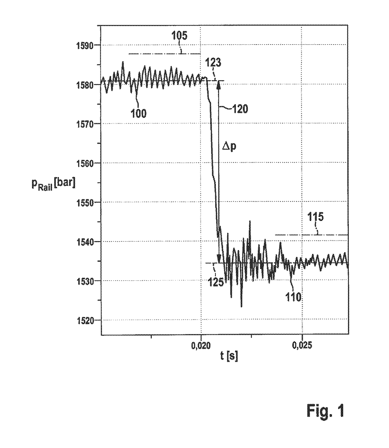
[0029]FIG. 1 shows an example of a rail pressure curve in a common rail injection system during an injection, which in the present example takes place at a point in time of approximately t=0.020 s. Shown pressure drop (Δp) 120 resulting from the injection, from an initial pressure 100 having a first average value 123 to a final pressure 110 having a second average value 125, is used as the basis for the method described below. These average values 123, 125 are formed in temporal evaluation windows 105, 115, respectively.

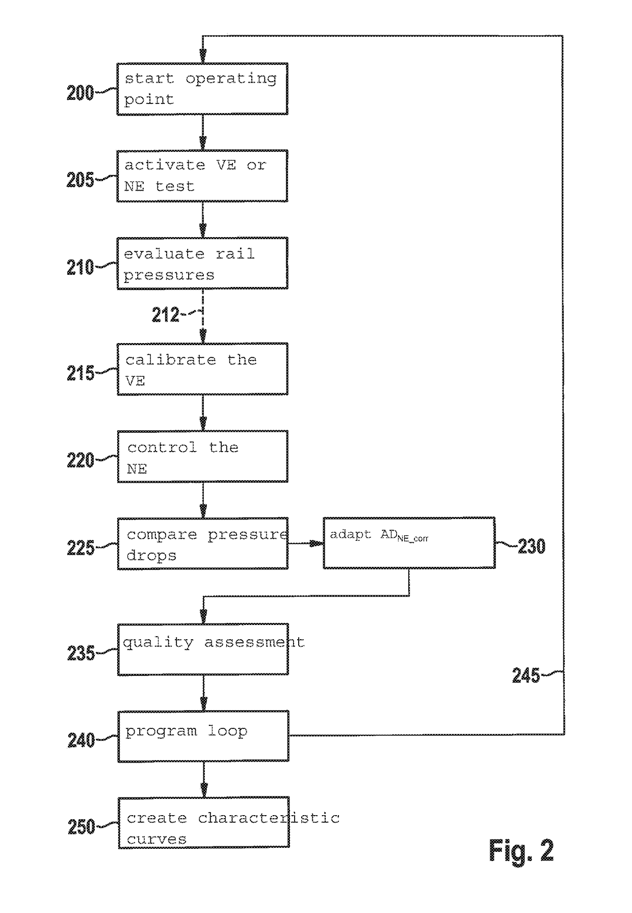
[0030]In the method shown in FIG. 2, the determination of the pressure drops of a pre-injection (VE) and a late post-injection (NE), as is apparent from FIG. 1, takes place based on the mentioned two evaluation windows 105, 115. In this exemplary embodiment, these evaluation windows have already been established during the manufacture of an internal combustion engine or an injection system, discussed here, of such an internal combustion engine, for example on an appr...


PUM


Abstract

A method for calibrating post-injections in a fuel injection system, including a fuel accumulator, of an internal combustion engine, in particular of a motor vehicle, in which it is provided in particular that the calibration of at least one post-injection takes place based on the pressure drop in the fuel accumulator caused by the fuel injection.

Description

FIELD[0001]The present invention relates to a method for calibrating post-injections in a fuel injection system of an internal combustion engine, in particular of a motor vehicle. Moreover, the present invention relates to a computer program, a machine-readable data medium for storing the computer program, and an electronic control unit with the aid of which the method according to the present invention may be carried out.BACKGROUND INFORMATION[0002]Compliance with present and future emission standards requires an exhaust aftertreatment in internal combustion engines. Thus, for example, conventionally, common rail diesel engines require a system for regenerating a particle filter which is provided for exhaust gas treatment, whereby structural engine measures must be taken in order to increase the filter temperature for purposes of regeneration, and optionally to set the recirculation rate of an exhaust gas recirculation (EGR) system with the aid of an EGR valve and / or to set the fee...

Claims


Application Information

Patent Timeline
Patent Type & Authority Applications(United States)
IPC IPC(8): F02D41/24F02D41/40
CPCF02D41/247F02D2200/0602F02D41/402F02D41/405F02D41/123F02D41/2467F02D41/403Y02T10/40
Inventor SCHENK, MICHAELZIEHER, RENE
Owner ROBERT BOSCH GMBH
Why Eureka
Try Eureka