Interior permanent magnet motor with flux strengthening

a permanent magnet motor and flux strengthening technology, applied in the field of permanent magnet motors, can solve the problems of increasing the total production cost of the motor b>30, and achieve the effect of lowering the production cos

Inactive Publication Date: 2017-06-01
NEW WIDETECH IND
View PDF4 Cites 11 Cited by
  • Summary
  • Abstract
  • Description
  • Claims
  • Application Information

AI Technical Summary

Benefits of technology

[0006]An objective of the present invention is to provide an interior permanent magnet motor with flux strengthening capable of getting rid of the use of power magnets and thus lowering production cost with regular permanent magnets.

Problems solved by technology

However, the permanent magnets 311 with higher magnetic force also come with a higher production cost, inevitably increasing the total production cost of the motor 30.

Method used


Image

  • Interior permanent magnet motor with flux strengthening
  • Interior permanent magnet motor with flux strengthening
  • Interior permanent magnet motor with flux strengthening

Examples


Embodiment Construction

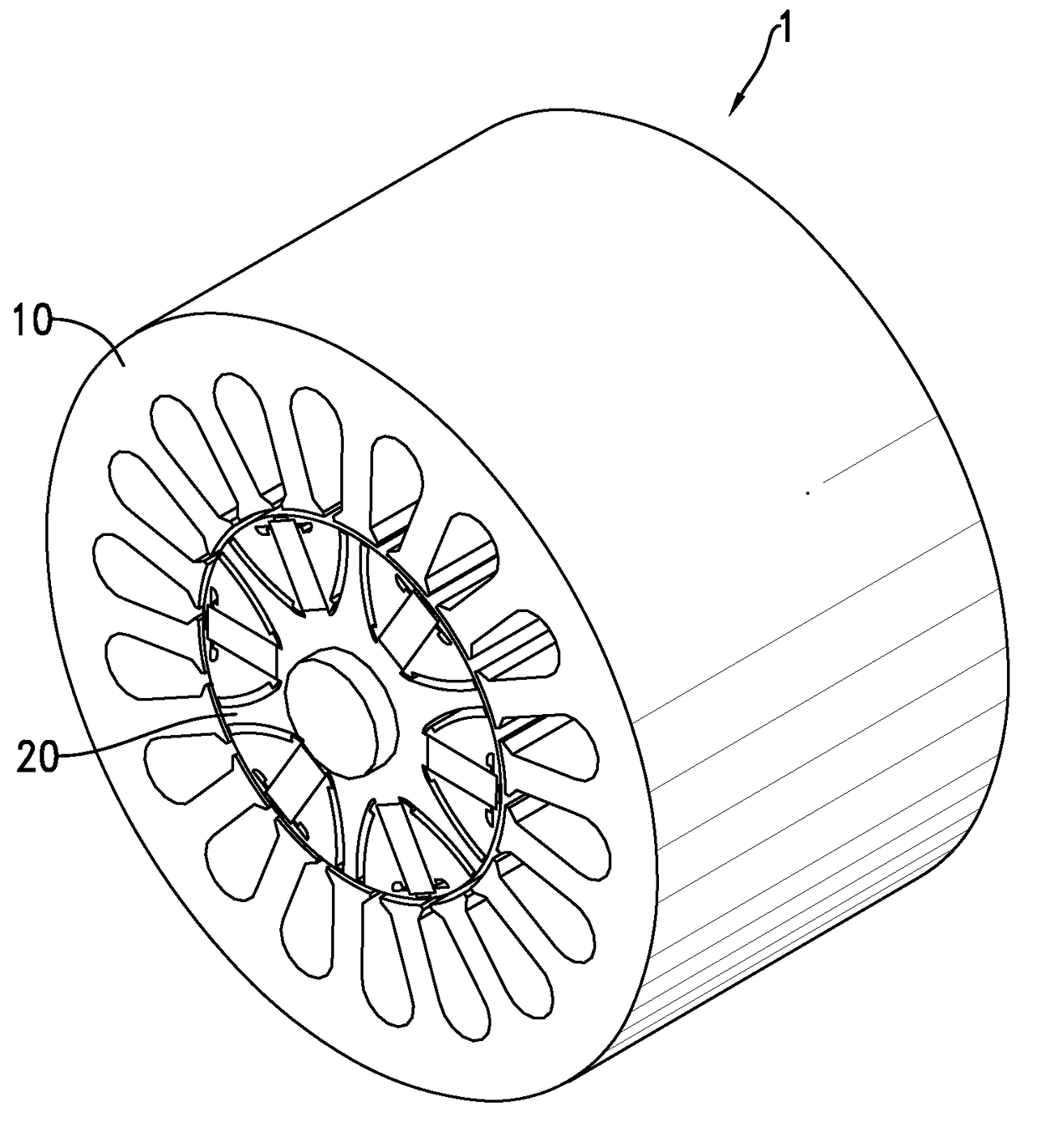
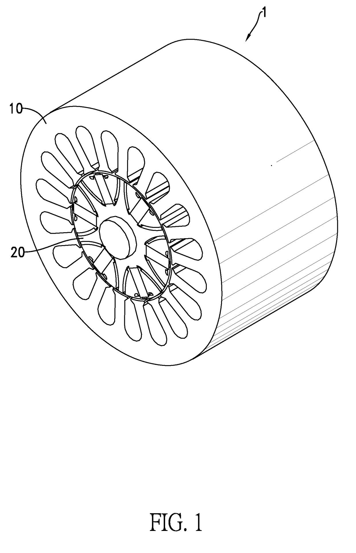
[0028]With reference to FIG. 1, a first embodiment of an interior permanent magnet motor with flux strengthening 1 in accordance with the present invention includes a stator 10 and a rotor 20.

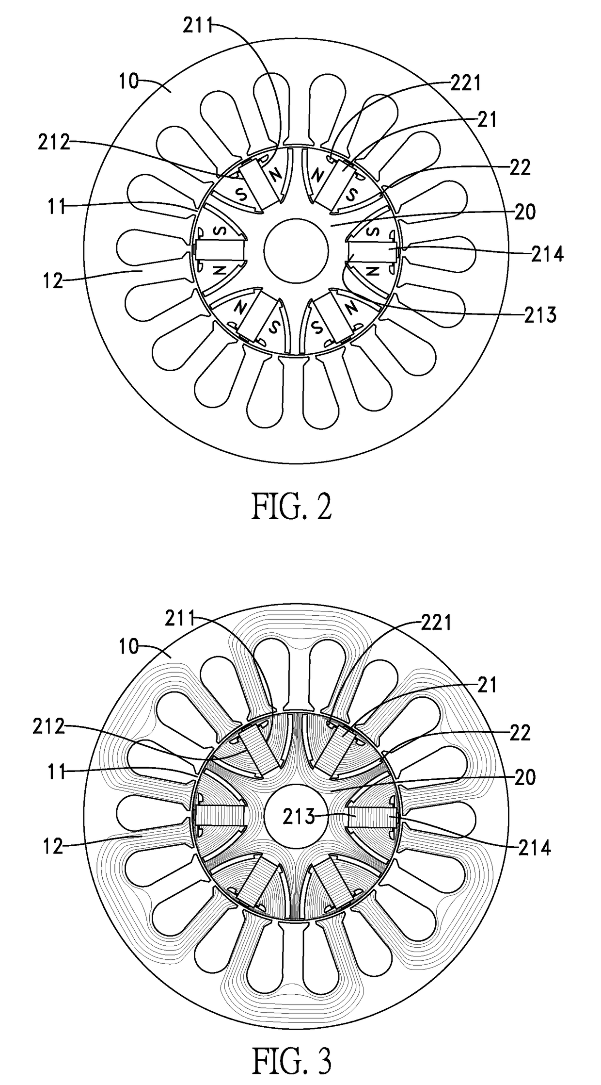
[0029]With reference to FIG. 2, the stator 10 in FIG. 1 is cylindrical and has a mounting hole 11 and multiple stator teeth 12. The mounting hole 11 is centrally and axially formed through the stator 10. The multiple stator teeth 12 are circumferentially and axially formed on and protrude radially and inwardly from an inner portion of the stator 10 between a periphery and the mounting hole 11 of the stator 10 and are spaced apart from each other. Each stator tooth 12 has a coil mounted around a periphery of the stator tooth 12.

[0030]The rotor 20 is cylindrical, is rotatably mounted inside the mounting hole 11 of the stator 10, and has multiple permanent magnets 21, multiple flux barrier grooves 22 and multiple short flux barrier grooves 221. The multiple permanent magnets 21 take the form of a ...


PUM


Abstract

An interior permanent magnet motor with flux strengthening includes a stator and a rotor. The stator has a mounting hole centrally formed through the stator and multiple stator teeth circumferentially formed on an inner portion of the stator between a periphery of the stator and the mounting hole. The rotor is rotatably mounted inside the mounting hole and includes multiple permanent magnets circumferentially and axially mounted inside the rotor. Each permanent magnet has two radial sides. The rotor further includes multiple flux barrier grooves. Each flux barrier groove is axially formed through a portion of the rotor located beside one of the two radial sides of a corresponding permanent magnet. The presence of the flux barrier grooves serves to shield and guide the lines of magnetic flux of the permanent magnets so as to concentrate the lines of magnetic flux, strengthen flux linkage, and reduce flux leakage.

Description

BACKGROUND OF THE INVENTION[0001]1. Field of the Invention[0002]The present invention relates to a permanent magnet motor and, more particularly, to an interior permanent magnet motor with flux strengthening.[0003]2. Description of the Related Art[0004]With reference to FIG. 10, all current air-conditioning compressors are equipped with a conventional motor 30 for attaining the purpose of conditioning air through operation of the motor. The conventional motor 30 includes a rotor 31 and a stator 32. There are six permanent magnets 311 annularly mounted around an inner wall of the rotor 31 and spaced apart from each other by gaps. The polarities of any adjacent two of the six permanent magnets 311 are reversed. The stator 32 has multiple stator teeth 321 with a coil mounted around each stator tooth 321. When current flows through the coils, each stator tooth 321 generates corresponding polarities according to the direction of current flow and attraction force and repulsion force actin...

Claims


Application Information

Patent Timeline
Patent Type & Authority Applications(United States)
IPC IPC(8): H02K1/27H02K1/02
CPCH02K1/02H02K1/2773
Inventor CHIU, MING-TSUNG
Owner NEW WIDETECH IND
Why Eureka
Try Eureka