Vehicle drive device

a technology of vehicle drive and drive device, which is applied in the direction of engine-driven generator propulsion, transportation and packaging, mechanical equipment, etc., can solve the problems of reduced mountability to a vehicle, reduced efficiency of vehicle drive device in the upward direction, and increased so as to reduce and suppress the increase of the protruding height of the motor control devi

Active Publication Date: 2017-06-08
AISIN AW CO LTD
View PDF32 Cites 14 Cited by
  • Summary
  • Abstract
  • Description
  • Claims
  • Application Information

AI Technical Summary

Benefits of technology

[0014]In order to reduce the protruding height of the motor control device, it is considered that the components of the motor control device are arranged in the vehicle front-rear direction. In this case, in order to cool the first inverter device and the second inverter device by the cooling unit, these components are integrated into one unit as an inverter unit, and then the inverter unit and the smoothing capacitor are arranged in the vehicle front-rear direction. Thus, it is possible to suppress an increase in the protruding height of the motor control device.
[0015]In the upward direction of the highest located member, the case projects upward, so that the height of the case tends to increase. According to the present configuration, one of the inverter unit and the smoothing capacitor having a smaller thickness in the vehicle up-down direction than the other is disposed in the upward direction of the highest located member. Accordingly, according to the present configuration, it is possible to effectively suppress an increase in the protruding height of the motor control device, and to compactly arrange the motor control device in the upward direction of the case of the vehicle drive device.

Problems solved by technology

Therefore, with this technique, when the motor control device is attached to a case of a vehicle drive device, the height of the motor control device protruding from the case is increased, which may result in a reduction in mountability to a vehicle.
Further, with this technique, the efficient utilization of the space in the upward direction of the vehicle drive device may not be achieved.
Further, as for this technique, the arrangement of a second inverter device for a pump electric motor is not described, so that an appropriate arrangement including the arrangement of the second inverter device has not been implemented.

Method used


Image

  • Vehicle drive device
  • Vehicle drive device
  • Vehicle drive device

Examples


Embodiment Construction

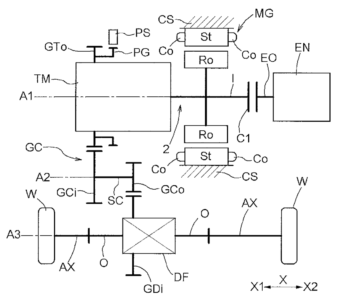
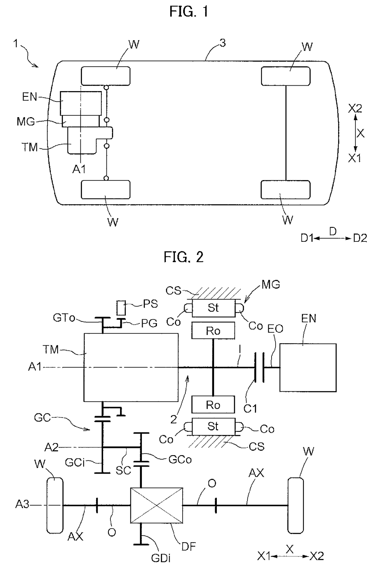
[0024]Hereinafter, an embodiment illustrating a vehicle drive device for a hybrid vehicle including an internal combustion engine and a rotary electric machine as a driving force source of the vehicle will be described with reference to the drawings. As illustrated in FIG. 2, a vehicle drive device 1 includes a wheel drive rotary electric machine MG and a transmission device TM on a power transmission path 2 connecting an input shaft I drivingly coupled to an internal combustion engine EN and output shafts O drivingly coupled to the wheels W. Also, as illustrated in FIGS. 4 and 5, the vehicle drive device 1 includes a pump electric motor EP that serves as a driving force source of a hydraulic pump, and a case CS that accommodates the wheel drive rotary electric machine MG, the transmission device TM, and the pump electric motor EP. Note that the input shaft I corresponds to an “input member”, and the output shafts O correspond to an “output member”.

[0025]As illustrated in FIG. 5, th...


PUM


Abstract

A vehicle drive device that includes a wheel drive rotary electric machine and a transmission device on a power transmission path connecting an input member drivingly coupled to an internal combustion engine and an output member drivingly coupled to wheels; a pump electric motor that serves as a driving force source of a hydraulic pump; a case that accommodates the wheel drive rotary electric machine, the transmission device, and the pump electric motor; and a motor controller including a first inverter that controls the wheel drive rotary electric machine, a second inverter that controls the pump electric motor, a cooler that cools the first inverter and the second inverter, and a smoothing capacitor that smooths direct-current power to be supplied to the first inverter and the second inverter.

Description

TECHNICAL FIELD[0001]The present invention relates to a vehicle drive device including: a wheel drive rotary electric machine and a transmission device on a power transmission path connecting an input member drivingly coupled to an internal combustion engine and an output member drivingly coupled to wheels; a pump electric motor that serves as a driving force source of a hydraulic pump; and a case that accommodates the wheel drive rotary electric machine, the transmission device, and the pump electric motor.BACKGROUND ART[0002]Techniques described in Japanese Patent Application Publication No. 2011-67093 (JP 2011-67093 A) (Patent Document 1) and Japanese Patent Application Publication No. 2007-118808 (JP 2007-118808 A) (Patent Document 2) are known in connection with the vehicle drive device described above. According to the technique described in JP 2011-67093 A, a first inverter device for a wheel drive rotary electric machine, a second inverter device for a pump electric motor, a...

Claims


Application Information

Patent Timeline
Patent Type & Authority Applications(United States)
IPC IPC(8): B60K6/40B60K6/48B60W20/00B60L11/14B60L50/16
CPCB60K6/40B60W20/00B60K6/48B60L11/14B60K6/405B60K2006/4825B60L1/02B60L15/007B60L50/16B60L2240/525B60L9/18F16H61/0006Y02T10/62Y02T10/64Y02T10/7072B60K6/54Y02T10/70
Inventor MIYAZAWA, MANABUUECHI, TATSUYUKI
Owner AISIN AW CO LTD
Why Eureka
Try Eureka