Fuel tank cleaning arrangement

Inactive Publication Date: 2017-06-08
MOTOREN & TURBINEN UNION FRIEDRICHSHAFEN GMBH
View PDF2 Cites 0 Cited by
  • Summary
  • Abstract
  • Description
  • Claims
  • Application Information

AI Technical Summary

Benefits of technology

The invention is about a tank cleaning arrangement that uses a mechanically driven circulation pump, which is independent of an electric power supply. This means that the pump doesn't need to be powered by electricity, so there is no need for complicated and expensive control systems and power supply lines. This arrangement also reduces the need for batteries to be used for driving the pump, which improves operational security and reduces maintenance and manufacturing costs. Additionally, the arrangement includes a control system that can determine the degree of contamination in different areas of the tank and prevent further filtering that may not improve the fuel quality. Overall, this tank cleaning arrangement is efficient, effective, and economical.

Problems solved by technology

With such an arrangement, also batteries possibly used for driving pumps cannot be excessively discharged since the circulation pump does not need to be operated by an electric motor when for example the control system fails or an appropriate control system is not present.

Method used


Image

  • Fuel tank cleaning arrangement
  • Fuel tank cleaning arrangement

Examples


Embodiment Construction

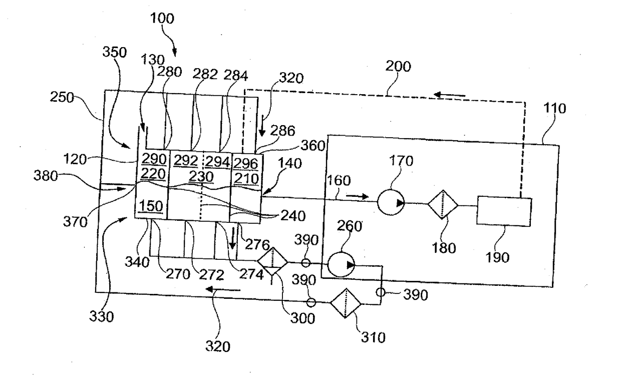
[0068]As shown in FIG. 1 a tank cleaning arrangement 100 can be provided in the form of a combination of a combustion engine 110 with a fuel tank 120.

[0069]Herein the fuel tank may have a main inlet 130 and a main outlet 140. The liquid fuel 150 stored in the fuel tank 120 can for example be used for operating the combustion engine 110 so that fuel 150 can be supplied to the combustion engine 110 from the main outlet area 140 via a supply line 160. In the supply line 160 an engine fuel pump 170 and an engine filter 180 may be arranged. In this way, it can be ensured that only sufficiently filtered fuel 150 is supplied to an injection device 190 of the combustion engine 110. In addition, a return line 200 may be provided by way of which the excessive fuel 150 can be returned from the injection device 190 to the fuel tank 120. Preferably, the fuel 150 is returned to a part 210 of the main outlet 140. In this way, advantageously it is ensured that the clean returned fuel mixes to a les...


PUM

PropertyMeasurementUnit
Timeaaaaaaaaaa
Flow rateaaaaaaaaaa

Abstract

In a tank cleaning arrangement for cleaning liquid fuel stored in a fuel tank, the fuel is circulated from various selectable outlet areas to various selectable inlet areas provided on the tank via a conduit system including circulating pumps and filters arranged at various locations. At least one circulating pump is driven mechanically by an engine associated with the tank cleaning arrangement, whereby the tank cleaning arrangement is shut down automatically when the engine is shut down, so that a control as well as a separate drive system for the at least one circulating pump can be omitted. Also a combustion engine with such tank cleaning system is and an operating method for the tank cleaning arrangement are disclosed.

Description

[0001]This is a Continuation-In-Part application of pending international patent application PCT / EP2015 / 001600 filed Aug. 4, 2015 and claiming the priority of German patent application 10 2014 016 457.8 filed Oct. 28, 2014.BACKGROUND OF THE INVENTION[0002]The invention concerns a tank cleaning arrangement for the cleaning of liquid fuel stored in a fuel tank including a circulation conduit system via which, with the fuel tank installed, the fuel is circulated from at least one outlet of the fuel tank to an inlet of the fuel tank with at least one fuel filter arranged in the circulation conduit system, and at least one circulation pump arranged in the circulation conduit system. Furthermore, the invention concerns a system comprising a fuel tank with a tank cleaning arrangement. In addition, the invention concerns an internal combustion engine with a fuel tank and a tank cleaning arrangement.[0003]Problems with the fuel do not only occur in connection with motor vehicles but for exam...

Claims


Application Information

Patent Timeline
IPC IPC(8): F02M37/22F02M37/04B01D35/26B01D35/00B01D35/143F02M37/24F02M37/40F02M37/42
CPCF02M37/22B01D35/005F02M37/04B01D35/26B01D35/143F02M37/0047F02M37/0052F02M37/007F02M37/40F02M37/24F02M37/42
Inventor REISCHMANN, WOLFGANG
Owner MOTOREN & TURBINEN UNION FRIEDRICHSHAFEN GMBH
Why Eureka
Try Eureka