Flow regulating system for supplying propellant fluid to an electric thruster of a space vehicle

Active Publication Date: 2017-06-08
SN DETUDE & DE CONSTR DE MOTEURS DAVIATION S N E C M A
View PDF17 Cites 2 Cited by
  • Summary
  • Abstract
  • Description
  • Claims
  • Application Information

AI Technical Summary

Benefits of technology

The invention allows for a single component, called a flow rate regulator, to do both flow rate regulation and flowmetering without needing to modify the structure of the component. This results in a lighter system and better accuracy than existing systems that have separate components for flow rate regulation and flowmetering.

Problems solved by technology

Nevertheless there is no relationship for reliably establishing a correlation between the heating current of the thermocapillary tube and the outgoing flow rate, while also taking account of the variables that influence this relationship, and in particular environmental parameters representing the ambient conditions in which the flow rate regulator is used.
Nevertheless, in space applications, such an increase in components for the purpose of performing a simple flow rate regulator function is problematic in that it adds additional mass, which is highly constraining, given the power needed to launch a given mass into geo-stationary orbit.
Such a method makes it possible to avoid installing a flowmeter, but is nevertheless not very accurate, and in order to conserve a safety margin, space vehicles that use such a method must therefore be put into end-of-life before the real end of total consumption of the propellant fluid.

Method used


Image

  • Flow regulating system for supplying propellant fluid to an electric thruster of a space vehicle
  • Flow regulating system for supplying propellant fluid to an electric thruster of a space vehicle

Examples


Embodiment Construction

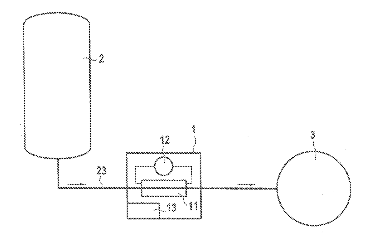
[0024]FIG. 1 shows diagrammatically a system in an aspect of the invention.

[0025]FIG. 1 shows a system for regulating the flow rate between a tank 2 of propellant fluid and an electrical thruster 3 that are connected together by a duct 23 having a flow rate regulator 1 arranged thereon.

[0026]By way of example the electrical thruster is a Hall effect engine, a pulsed plasma thruster, an ion thruster, or more generally any electrical thruster using a propellant fluid.

[0027]The flow rate regulator 1 comprises a heater element 11, typically powered by a generator 12 and controlled by a computer 13. The heater element 11 applies direct or indirect heating to the propellant fluid flowing in the duct 23, with the magnitude of the current being controlled by the computer 13. The flow rate regulator 1 is typically arranged at the outlet from the tank 2.

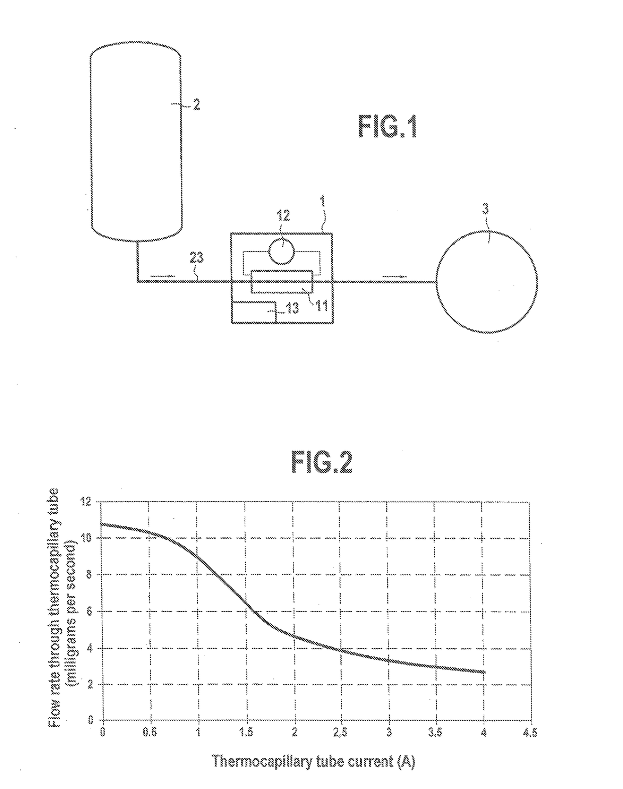
[0028]Heating the propellant fluid serves to modify the physical properties of the propellant fluid, thereby modifying head losses in the duc...


PUM


Abstract

A system for regulating the flow rate of a propellant fluid for an electrical thruster of a space vehicle, the vehicle including a tank of propellant fluid and a flow rate regulator connected to the outlet of said tank;the flow rate regulator including a heater element controlled by a computer and adapted to heat the propellant fluid and to modify its physical properties so as to vary the flow rate of propellant fluid leaving the tank;said system being characterized in that the computer also includes a plurality of empirical calibration curves that have been determined empirically for defining the flow rate of propellant fluid as a function of the magnitude of heating and as a function of environmental parameters, such that said computer also performs a function of determining the flow rate of the propellant fluid.

Description

GENERAL TECHNICAL FIELD[0001]The present invention relates to the field of electrical thrusters such as in particular Hall effect engines, and more precisely to the field of means for controlling the flow rate of propellant fluid delivered to an electrical thruster in the context of an application for a space vehicle.STATE OF THE ART[0002]In electrical thrusters, the propellant fluid is stored within a tank. The tank is provided with and connected to control means in order to deliver a given flow rate to ensure proper operation of the electrical thruster.[0003]Such control means typically comprise a flow rate regulator commonly referred to as a flow control unit (FCU) or as a xenon flux controller (XFC) when the propellant fluid is xenon, which regulator performs controlled heating of the fluid by means of a thermocapillary tube in order to modify the physical properties of the fluid, and thus its flow rate at the outlet from the tank.[0004]Nevertheless there is no relationship for ...

Claims


Application Information

Patent Timeline
IPC IPC(8): F03H1/00B64G1/40
CPCF03H1/0012F03H1/0031B64G1/405B64G1/402F03H1/0062
Inventor VIAL, VANESSALORAND, ANTHONYGIBOUDEAUX, KEVINLEROI, VAITUA
Owner SN DETUDE & DE CONSTR DE MOTEURS DAVIATION S N E C M A
Why Eureka
Try Eureka