
Tension spring mount with friction-resistant coating

Active Publication Date: 2013-08-08
RENTON COIL SPRING
View PDF9 Cites 11 Cited by
  • Summary
  • Abstract
  • Description
  • Claims
  • Application Information

AI Technical Summary

Benefits of technology

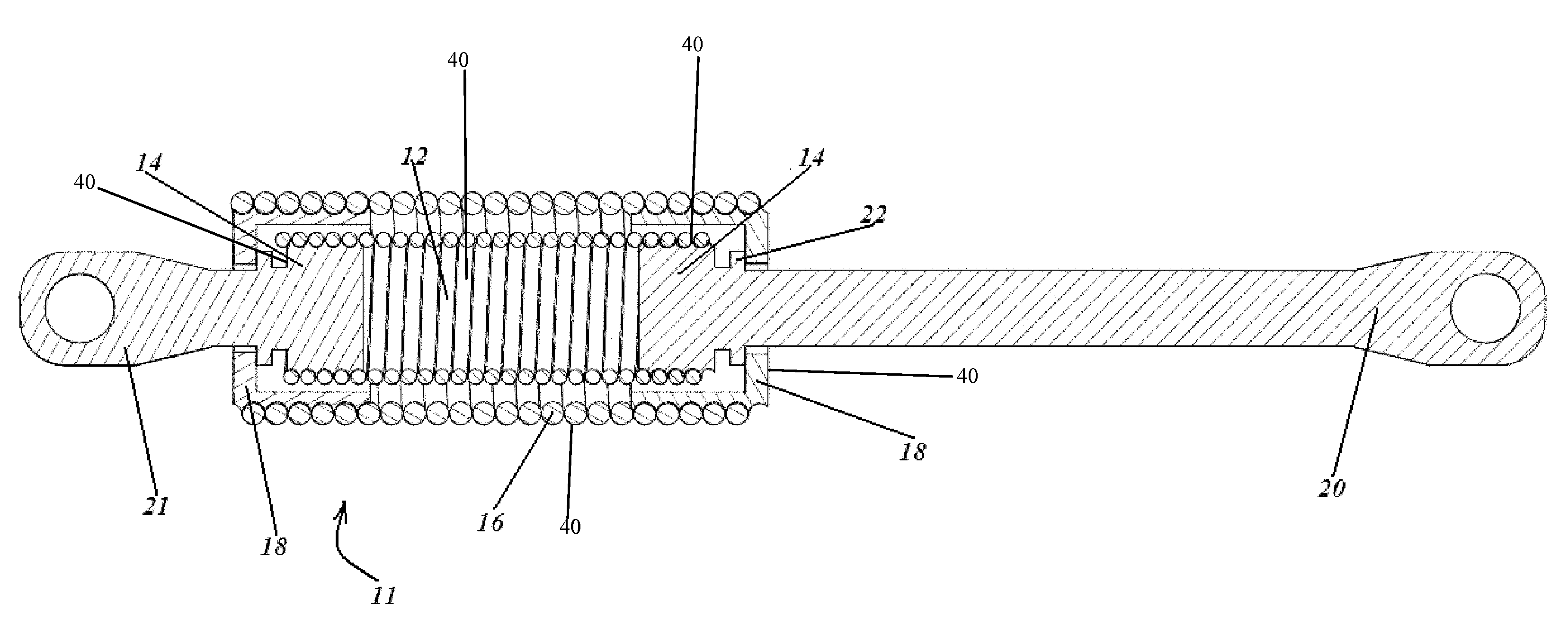
The invention describes a new system of springs that allows for a reduction in mass and increases the strength of the system. This system also adds an extra measure of safety by introducing another spring to the mix. Additionally, the resonant frequency of the combined spring system is significantly changed, which can improve safety by avoiding dangerous frequency coupling. Overall, this invention provides a more secure, clean attachment that adds a factor of safety, is reliable, and saves weight.

Problems solved by technology

In a single-spring system however, when the spring fails, the whole system fails.
If one spring fails, the other can still properly function for a time until the broken spring is replaced.
In some cases, the springs wear, twist, or bend excessively where portions of the spring contact one another.
Also, some materials are abrasive, such as Titanium, and wear more quickly than other materials.

Method used


Image

  • Tension spring mount with friction-resistant coating
  • Tension spring mount with friction-resistant coating
  • Tension spring mount with friction-resistant coating

Examples


Embodiment Construction

[0021]As illustrated in FIG. 1, prior-art nested tension springs 4, 6 use opposing hooks to restrain the spring from releasing from their mount locations. The outer hook 10 opposes the inner hook 8. It is to be noted that the previous tension springs 4, 6 typically failed at the hook most particularly at the location where the large bending stress on the hook met the large torsion stress coming from the coil under a tensile load. The relationship of the hooks 8, 10 to the springs 4, 6 will be better understood after the following description. The operation of the springs 4, 6 may be understood upon reference to FIG. 1. The embodiment consists of two tensions springs 4, 6, an inner spring 4 and an outer spring 6. The above springs 4, 6 connect at hooks 8, 10 on either end. These springs 4, 6 are assembled together so that the coiled spirals are wound in opposing directions. The hooks 8, 10 however, are connected to fixtures in such a manner that upon application of repeated tensile f...


PUM


Abstract

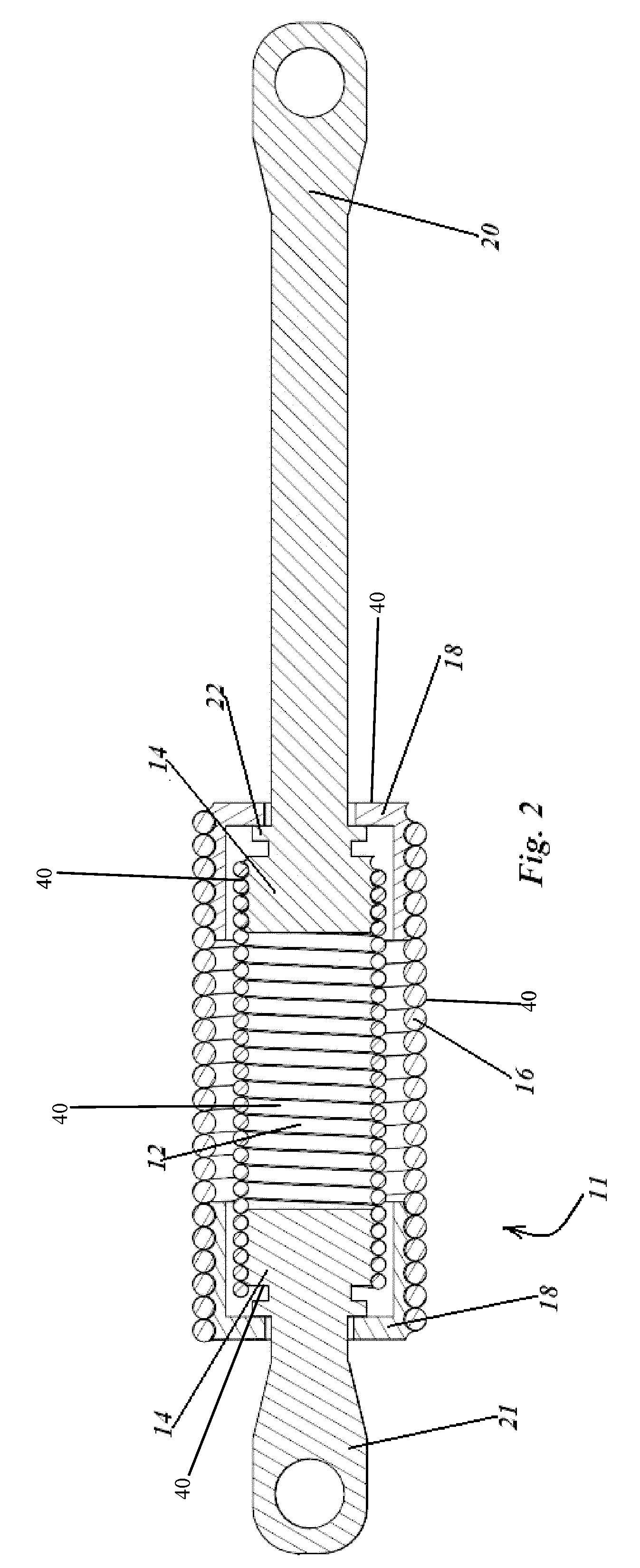
End mounts are used to secure a helical tension spring to end fixtures with various shapes and sizes. These end mounts contain an inner hole to encase the inner spring end mount and secure the end mount making it like a cap. There is also a keyhole created in the top surface that goes through the end mount allowing it to fit over the fixtures but not over the inner end mount, holding it in place. Grooves are machined in a helical pattern on the cylindrical side wall of the end mount. The spring is wound onto the grooves of the end mount. A friction-resistant coating is applied between components of the assembly to mitigate wear and to prevent bending and twisting.

Description

PRIORITY CLAIM[0001]This application is a continuation-in-part of co-pending U.S. patent application Ser. No. 12 / 710,899 filed Feb. 23, 2010, which is incorporated herein by reference in its entirety.FIELD OF THE INVENTION[0002]This invention relates generally to mounts for springs and, more specifically, to end-mounting tension springs and associated friction-resistant coatings.BACKGROUND OF THE INVENTION[0003]Nested springs are used for various applications. For example, they can be used in the landing gear of airplanes, or on any type of device for securing fixtures to a relatively moving component. They have been used where reliability is paramount or in some situations to reduce the space envelope required where the spring is mounted. Examples of applications of nested springs are throttle return springs, brake return springs, and valve springs.[0004]Often, nested springs are used to avoid single-point failures by providing a redundant system. They replace a single-spring syste...

Claims


Application Information

Patent Timeline
IPC IPC(8): F16F1/12F16F3/06
CPCF16F1/12F16F3/06F16F2236/06F16F3/04F16F1/125
Inventor PEPKA, CHARLES F.
Owner RENTON COIL SPRING
Learn More