Composite tip shroud ring

Inactive Publication Date: 2008-07-01
FLORIDA TURBINE TECH
View PDF5 Cites 60 Cited by
  • Summary
  • Abstract
  • Description
  • Claims
  • Application Information

AI Technical Summary

Benefits of technology

[0010]The object of the present invention is to provide a tip shroud ring on a row of turbine blades that will provide an improved seal between adjacent blades as well as reducing the mass of the tip shrouds in order to allow for a larger diameter of turbine blades. This objection is accomplished by proving a tip shroud ring that is completely annular in shape (360 degrees) and is formed from fiber reinforced ceramic composites. This ring is strong enough to carry its own weight (below its self-containing radius, or maximum radius at which a certain mass will break under the centrifugal force due to rotation). The ann

Problems solved by technology

This matching of frequencies could produce resonant vibration in the blade, which can cause damage to the blade.
Thus, the blade diameter—an

Method used


Image

  • Composite tip shroud ring
  • Composite tip shroud ring

Examples


Embodiment Construction

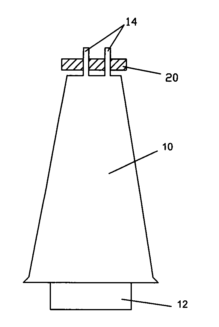
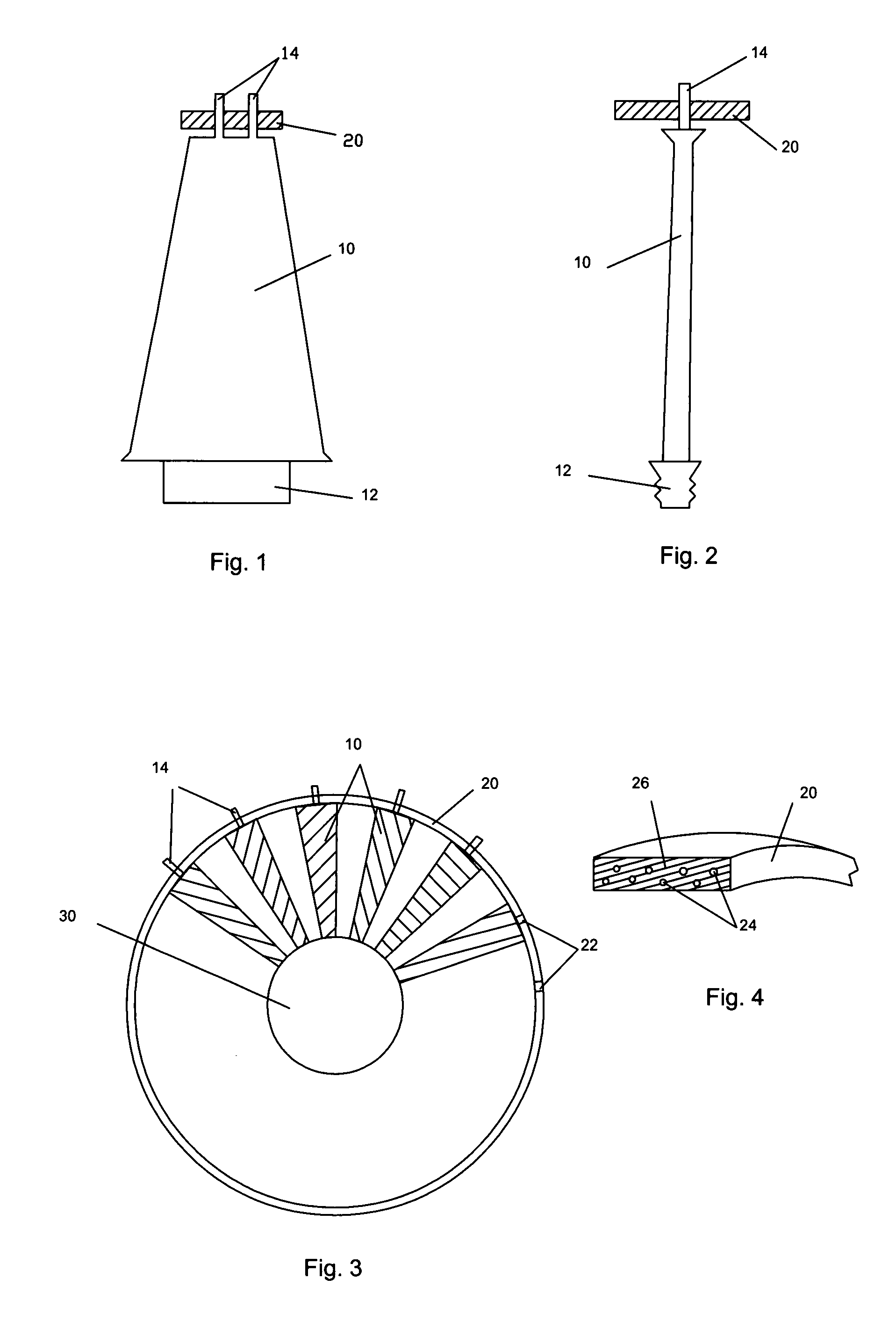
[0015]As shown in FIG. 3, a rotor includes a rotor disc 30 with slots extending around the circumference of the rotor disc 30. A plurality of turbine blades 10 extends from the rotor disc 30 outward. FIG. 3 shows only 6 of the blades in a 90 degree sweep of the rotor disc, but in actuality will extend the full 360 degrees around the rotor disc. The turbine blades 10 each include a root 12 (FIGS. 1 and 2) having a well-known fir tree configuration. The root 12 of each blade 10 slides within the slot of the rotor disc 30, and is held in place by any of the well known retaining means of the prior art. Each blade 10 includes two pins 14 extending from the tip end of the blade 10.

[0016]The inventive concept of this invention is shown in FIG. 1 and includes a tip shroud ring 20 formed as a single annular ring of a full 360 degrees. The ring 20 includes holes 22 therein positioned to accept the pins 14 of the blades. The holes 22 in the ring are sized such that the pins 14 of the blade can...


PUM

PropertyMeasurementUnit
Forceaaaaaaaaaa
Displacementaaaaaaaaaa

Abstract

A gas turbine engine includes a tip shroud ring rotatably supported on a last stage blade assembly in a turbine. The tip shroud ring is formed entirely of a fiber reinforced ceramic matrix composite material to provide a very light weight tip shroud ring, but also a very strong ring. The blades include pins extending from the tips, and the tip shroud ring includes holes in which the pins slide. Thus, the tip shroud ring is completely supported by the blade tip pins, and the centrifugal force developed by the rotation of the tip shroud ring does not add to the tensile force developed along the blades. Thus, the maximum rotational speed of the turbine rotor as defined by An2 can be increased. Also, because the blade tips are secured to the tip shroud ring in a circumferential direction, the tip shroud ring acts to dampen the bladed turbine by allowing only the middle of the blade to vibrate.

Description

CROSS-REFERENCE TO RELATED APPLICATIONS[0001]This application claims the benefit of a prior filed and U.S. Provisional Application, Ser. No. 60 / 677,898 filed on May 5, 2005 and entitled Composite Tip Shroud Ring.BACKGROUND OF THE INVENTION[0002]1. Field of the Invention[0003]This Invention relates to the field of Gas Turbine Engines, and, more specifically, to an annular tip shroud for a full row of rotating turbine blades.[0004]2. Description of the Related Art[0005]Rotating blades in a gas turbine engine are known to include tip shrouds to provide a gas seal for the flow path through the turbine, to provide a change in vibration response, and to provide vibration damping of the blades. A tip shroud will add mass to the blade, which will increase the pull and airfoil stress of the specific blade. A designer typically will use the tip shroud for a set of blades in a particular row to control the modal frequency of the blade such that the natural frequency of the blade will not coinc...

Claims


Application Information

Patent Timeline
IPC IPC(8): F01D5/22
CPCF01D5/143F01D5/225F05D2300/603F05D2300/21
Inventor MATHENY, ALFRED PAUL
Owner FLORIDA TURBINE TECH
Why Eureka
Try Eureka