
Concentric Camshaft and Method of Manufacturing Rotatable Cam and Fixed Cam for Concentric Camshaft

a technology of concentric camshafts and fixed cams, which is applied in the direction of manufacturing tools, valve drives, machines/engines, etc., can solve the problems of increasing the amount of waste materials, increasing the weight, and inability to provide compact parts, so as to improve the hardness of the cam surface, reduce the amount of machining, and simplify the manufacturing process

Inactive Publication Date: 2017-06-08
SEOJINCAM CO LTD
View PDF3 Cites 0 Cited by
  • Summary
  • Abstract
  • Description
  • Claims
  • Application Information

AI Technical Summary

Benefits of technology

The patent describes a new method of manufacturing a concentric camshaft that reduces the amount of machining needed and simplifies the process. The cam and inner piece are fixed through diffusion bonding, which eliminates the need for a heat treatment to improve cam surface hardness. This makes the camshaft ideal for engines with limited space. The method also reduces wear and waste during machining, which increases durability and decreases manufacturing costs. Additionally, the cam has a weight-reducing structure and is securely fixed using a spiral spring. A key groove is formed in the inner piece to improve pin press-fitting, and a second through-hole is formed in the rotatable cam to further reduce weight. Overall, the method improves the efficiency and reliability of the concentric camshaft.

Problems solved by technology

However, in the manufacturing method of the related art, a round bar including a can and a pin fixing section should be processed, and thus an amount of waste materials is increased.
In addition, in the manufacturing method of the related art, in order to improve workability during forging, a gradient is needed at a boundary between the cam and the pin fixing section to cause an increase in weight due to unnecessary reinforcement.
Further, since the pin fixing section should have a certain width or more, compact parts cannot be provided.

Method used


Image

  • Concentric Camshaft and Method of Manufacturing Rotatable Cam and Fixed Cam for Concentric Camshaft
  • Concentric Camshaft and Method of Manufacturing Rotatable Cam and Fixed Cam for Concentric Camshaft
  • Concentric Camshaft and Method of Manufacturing Rotatable Cam and Fixed Cam for Concentric Camshaft

Examples


first embodiment

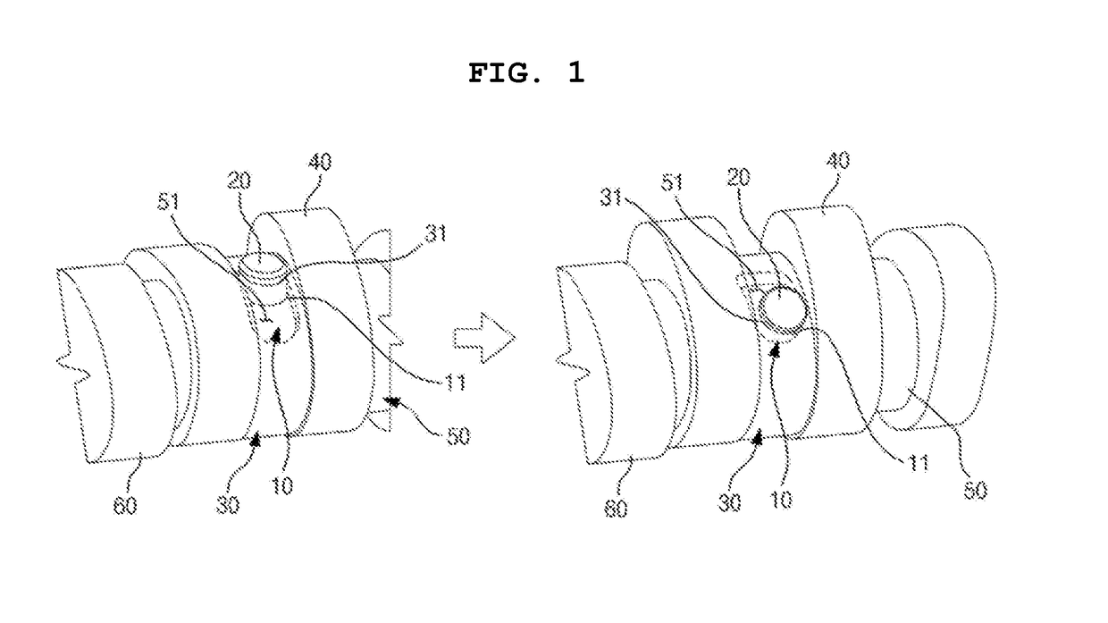
[0026]As shown in FIGS. 1 and 2, a concentric camshaft of a first embodiment includes a fixing section provided with an outer shaft 50 having a long hole 51 and a fixed cam 60 fixed to an outer circumferential surface of the outer shaft 50; and a rotatable section provided with an inner shaft 10 inserted into the outer shaft 50, a rotatable cam 40 disposed outside the outer shaft 50, and a pin 20 configured to connect the rotatable cam 40 and the inner shaft 10 and inserted into the long hole 51, wherein at least one of the fixed cam 60 and the rotatable cam 40 is fixed to inner pieces 30 and 70 disposed outside the outer shaft 50 through diffusion bonding.

[0027]The fixing section includes the outer shaft 50 having the long hole 51, and the fixed cam 60 fixed to the outer circumferential surface of the outer shaft 50.

[0028]The outer shaft 50 is a pipe in which a first hollow section is formed, and the long hole 51 in communication with the first hollow section is formed in the circu...

second embodiment

[0069]Detailed description and illustration of the same configuration as the above-mentioned embodiment will be omitted.

[0070]As shown in FIGS. 3 to 9, in a concentric camshaft according to a second embodiment, the rotatable section has one rotatable cam 40 fixed to one inner piece 30′.

[0071]The rotatable section may be disposed at one side of the one fixed cam 60 or may be disposed at both sides of the one fixed cam 60.

[0072]In addition, as shown in FIGS. 5 to 7, side sections (one side or both sides) of the rotatable cam 40 are reduced in weight, and grooves 42′ and 42 are formed at one side or both sides. The grooves 42′ and 42 are formed to be in communication with the second through-hole. The side sections are surfaces disposed at both sides perpendicular to the axis of the rotatable cam 40.

[0073]Further, as shown in FIGS. 6 and 7, the groove 42′ formed at one side may have an opening section 43 formed at a lower portion thereof. The opening section 43 is in communication with ...

third embodiment

[0080]Detailed description and illustration of the same configuration as the above-mentioned embodiment will be omitted.

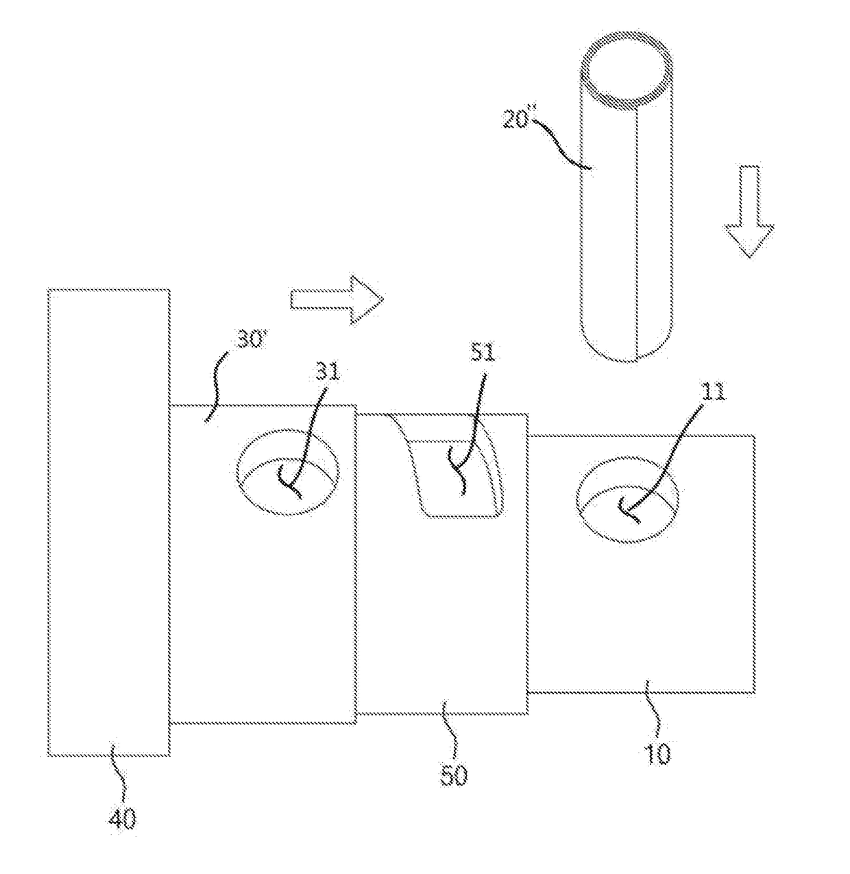
[0081]In a concentric camshaft according to a third embodiment, as shown in FIG. 10, a pin 20″ may include a spiral spring that can be elastically deformed. When the pin 20″ is formed of a spiral spring, an outer diameter of the pin 20″ can be elastically deformed to be reduced (contracted) upon press-fitting of the pin 20″ to easily press-fit the pin 20″, and the pin 20″ can be securely fixed due to a recovering force (expansion) of the elastically deformed pin 20″ after press-fitting of the pin 20″.


PUM

PropertyMeasurementUnit
Weightaaaaaaaaaa
Hardnessaaaaaaaaaa

Abstract

Provided is a concentric camshaft and a method of manufacturing the same, in which at least one of a fixed cam and a rotatable cam is a sintered cam configured to fix the cam and an inner piece through diffusion bonding, capable of reducing a machining amount, simplifying a manufacturing process because a heat treatment process for improving cam surface hardness is unnecessary, and being applied to an engine having a small space because the weight is reduced through a weight-reducing structure of a surface of the cam and a width of the inner piece is reduced.

Description

TECHNICAL FIELD[0001]The present invention relates to a concentric camshaft and a method of manufacturing the same, and more particularly, to a concentric camshaft and a method of manufacturing the same, in which at least one of a fixed cam and a rotatable cam is a sintered cam configured to fix the cam and an inner piece through diffusion bonding.BACKGROUND ART[0002]A concentric camshaft of the related art is disclosed in US Patent Application Publication Nos. 2012-0260873 and 2010-0170458.[0003]In US Patent Application Publication Nos. 2012-0260873 and 2010-0170458, a pin fixing section expanded in an axial direction is provided to fix a rotatable cam to a shaft using a pin. The cam is integrally formed through forging or round bar machining.[0004]However, in the manufacturing method of the related art, a round bar including a can and a pin fixing section should be processed, and thus an amount of waste materials is increased. In addition, in order to increase surface hardness aft...

Claims


Application Information

Patent Timeline
IPC IPC(8): F16H53/02B21D53/84B23K20/02F01L1/047
CPCF16H53/025F01L1/047F01L2103/00B23K20/02F01L2001/0473B21D53/845F01L1/08F01L13/0036F01L2001/0471F01L2303/00
Inventor KIM, YONG KYOONPARK, YUNG SANGSONG, JUN HOKANG, KEUN HOSONG, JONG HUN
Owner SEOJINCAM CO LTD
Features
  • Generate Ideas
  • Intellectual Property
  • Life Sciences
  • Materials
  • Tech Scout
  • Unparalleled Data Quality
  • Higher Quality Content
  • 60% Fewer Hallucinations
Learn More