
Residue cancellation for automated vehicle MIMO radar

a technology of automated vehicles and residues, applied in diversity/multi-antenna systems, instruments, and reradiation, etc., can solve the problems of reducing the detection performance of objects, tdm introduces the ineffective use of the coherent processing interval (cpi) of the radar measurement, and the method has performance/cost trade-offs, so as to improve the limitation of pseudo-random phase modulation (prpm) and reduce the residue level

Active Publication Date: 2017-06-08
APTIV TECH LTD
View PDF0 Cites 33 Cited by
  • Summary
  • Abstract
  • Description
  • Claims
  • Application Information

AI Technical Summary

Benefits of technology

The patent describes a way to improve the performance of a radar system by reducing the level of residue. This technique involves processing the radar signals in a way that reduces the impact of a certain type of modulation, which can affect the quality of the radar system. The result is better performance and more accurate data collection.

Problems solved by technology

Each of these methods has performance / cost trade-offs.
However, TDM introduces the ineffective usage of the coherent processing interval (CPI) of the radar measurement.
This will degrade the radar's object detection performance by reducing the detection sensitivity (through time multiplexing losses) and the ability to unambiguously measure Doppler across a wide interval (by increasing the time between pulses from a single transmit antenna).
The cost of this approach is that an increased baseband bandwidth is required to sample the signals received from the multiple transmit antennas.
Also, the unambiguous range coverage is impacted.
The downside of this approach is that the shift in frequency of the received signal from one object can interfere with the signal from another.
However, this alternative results in increased system cost and complexity.
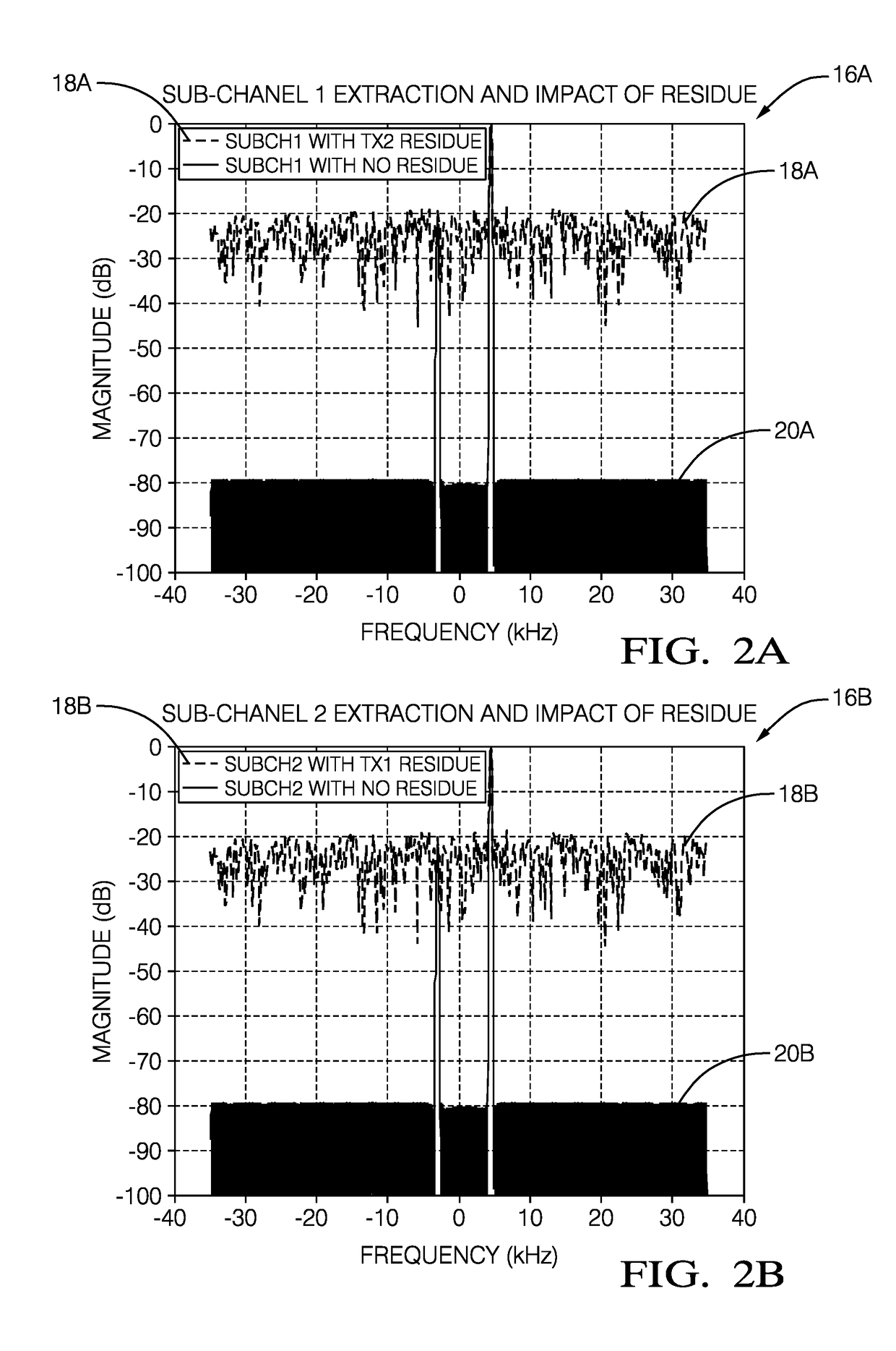
A limitation of this approach is that, upon demodulation for a given transmit antenna, the energy of the suppressed signals from the other transmit antennas is still present in the recovered signal for the given transmit antenna, but merely distributed across a frequency band.
The presence of this residue limits the ability of the radar system to unambiguously extract the signal reflected from a smaller object in the presence of a signal reflected from a larger object.
However, for some designs, increasing the code length for significant improvement in residue may not be practical or may have cost and performance implications on the system design.
However, its calculation is complex and time-consuming, and generally not practical for low-cost automotive radar.

Method used


Image

  • Residue cancellation for automated vehicle MIMO radar
  • Residue cancellation for automated vehicle MIMO radar
  • Residue cancellation for automated vehicle MIMO radar

Examples


Embodiment Construction

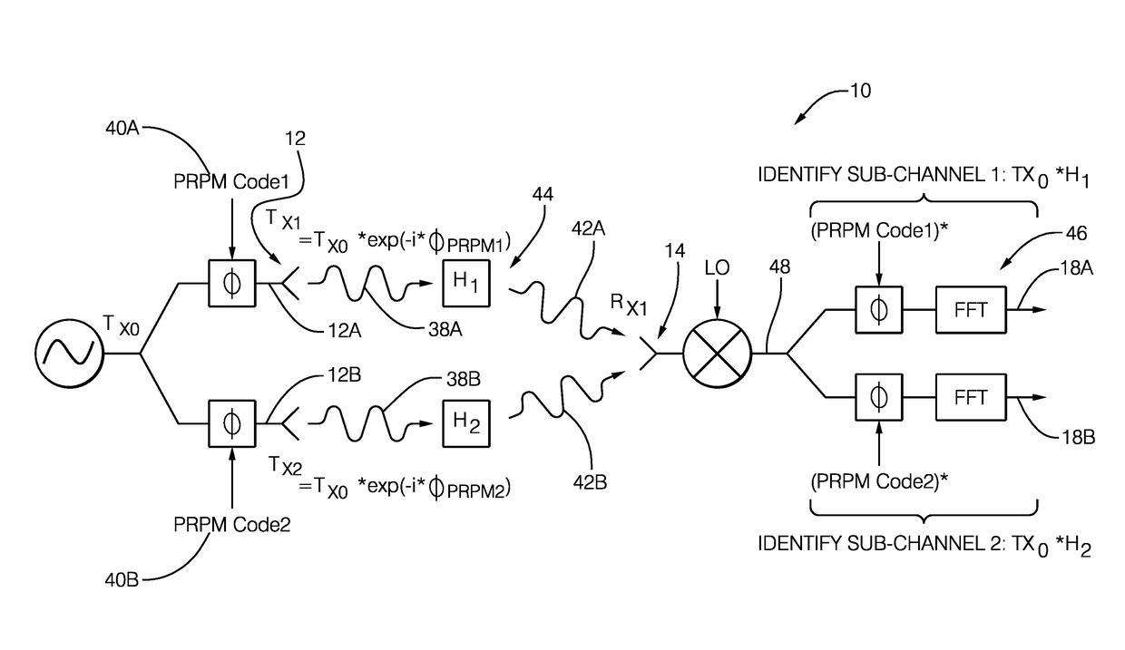
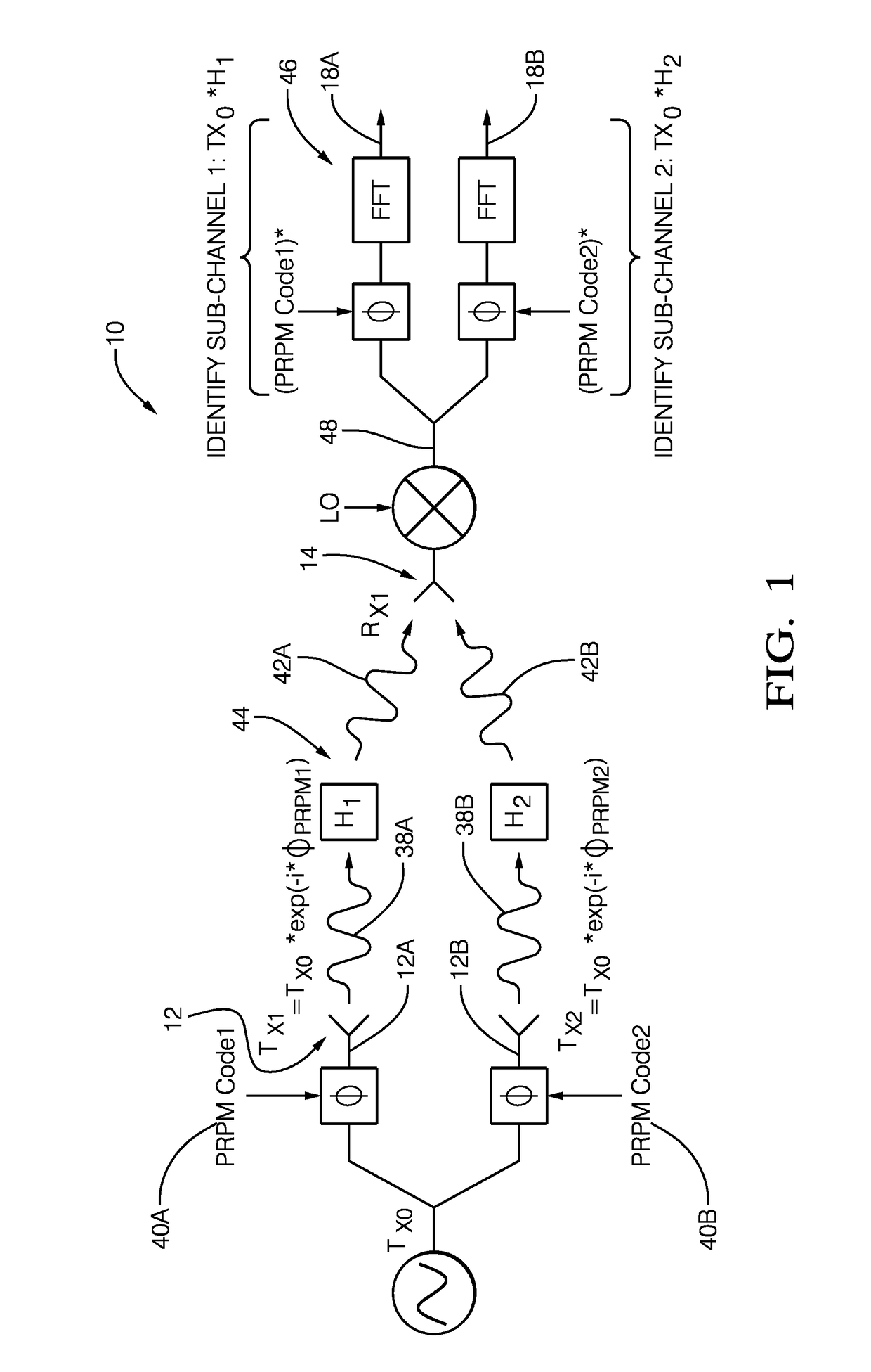
[0031]FIGS. 1 and 3 illustrate non-limiting examples of a PRPM MIMO Radar system, hereafter referred to as the system 10, with sub-channel extraction for the simple case of two transmit antennas and one receive antenna. A paper entitled MIMO Imaging Radar with Enhanced Range-Azimuth Sidelobe Suppression by T. Takayama, Y. Tokieda, and H. Sugawara, published in the Proc. IET Int. Radar Conf. (2012) describes an implementation of a pseudo-random phase code both within a chirp and between chirps for a MIMO radar system that illustrates residue for a single chirp and for integrated chirps. Pseudo-Random Phase Modulation is a method of digital modulation in which the phase of a signal sent to each transmit antenna is randomly varied in order to achieve a degree of orthogonality between simultaneously transmitted and received signals. The degree of orthogonality between signals depends on the ability of the phase modulation to distribute energy of the signals to be later effectively suppr...


PUM


Abstract

A Pseudo-Random Phase Modulation (PRPM) multiple-input-multiple-output (MIMO) radar system suitable for use on an automated vehicle includes a first transmit-antenna that transmits a first transmit-signal generated by a first PRPM-code, a second transmit-antenna that transmits a second transmit-signal generated by a second PRPM-code, a receive-antenna used to detect a first reflected-signal arising from the first transmit-signal and a second reflected-signal arising from the second transmit-signal, and a controller. The controller is in communication with the receive-antenna and is operable to generate the first PRPM-code and the second PRPM-code. The controller is configured to generate a first sub-channel-output based on a down-converted-signal from the receive-antenna and the first PRPM-code, generate a second sub-channel-output based on the down-converted-signal from the receive-antenna and the second PRPM-code, determine a first residue-signal based on the second sub-channel-output, and determine a first residue-removed-signal by subtracting the first residue-signal from the first sub-channel-output.

Description

TECHNICAL FIELD OF INVENTION[0001]This disclosure generally relates to a multiple-input-multiple-output (MIMO) radar system, and more particularly relates to the cancellation of signal residue arising from demodulation of a received signal.BACKGROUND OF INVENTION[0002]Automotive radar sensors are widely used in automated vehicle sensing systems in order to provide information about the surrounding environment to control operation of the automated vehicle and / or to use in Advanced Driver Assistance Systems (ADAS) features. Radar systems may employ a variety of techniques to determine or measure the angle of arrival of a reflected signal. In this way, the angular direction of an object can be estimated. One technique known as Digital Beamforming uses an array of antennas to receive a signal that was reflected by an object. By analyzing the relative phase of the reflected signal across the array of antenna elements the angle from which the signal is received can be determined.[0003]For...

Claims


Application Information

Patent Timeline
Patent Type & Authority Applications(United States)
IPC IPC(8): G01S7/32H04B7/04G01S13/931
CPCH04B7/0413G01S7/32G01S7/36G01S7/411G01S7/038G01S7/2921G01S13/42G01S13/931G01S13/288G01S7/2883
Inventor SEARCY, JAMES F.ARAGE, ALEBEL HASSENALLAND, STEPHEN W.CAO, SIYANG
Owner APTIV TECH LTD
Learn More