Electric connecting terminal

Active Publication Date: 2017-06-08
JOINSET
View PDF4 Cites 4 Cited by
  • Summary
  • Abstract
  • Description
  • Claims
  • Application Information

AI Technical Summary

Benefits of technology

[0016]An object of the present invention is to provide an electric connecting termina

Problems solved by technology

According to such a structure, an adhering process is included and makes a manufacturing process complicated, and there is a limit in reducing the size.
In particular, when each of the diameter and height is 1 mm or shorter, it is difficult to manufacture the electric contact terminal.
In the foregoing structure, since a metal sheet is pressed to manufacture the movable member and the fixing member, a metallic spring is inserted therebetween, and then the fixing member is pressed again to be coupled to the movable member, it is expensive and hard to assemble.
In particular, when each of the diameter and height of the electric connecting te

Method used


Image

  • Electric connecting terminal
  • Electric connecting terminal
  • Electric connecting terminal

Examples


Embodiment Construction

[0038]Now, exemplary embodiments of the present invention will be described in detail with reference to the accompanying drawings.

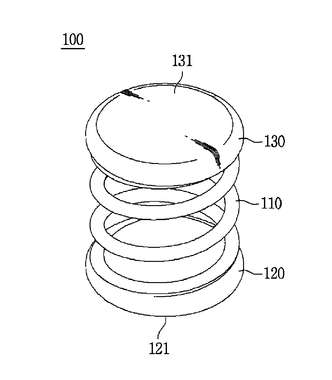
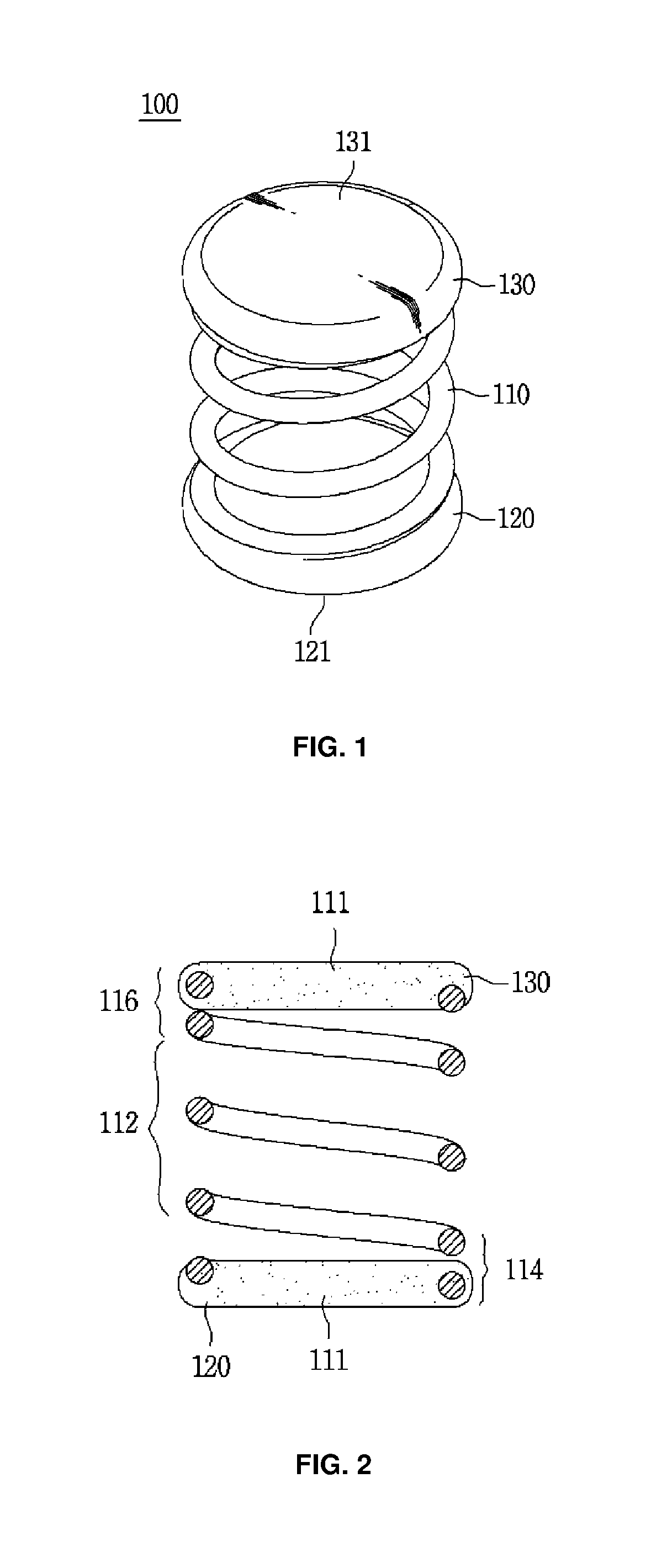
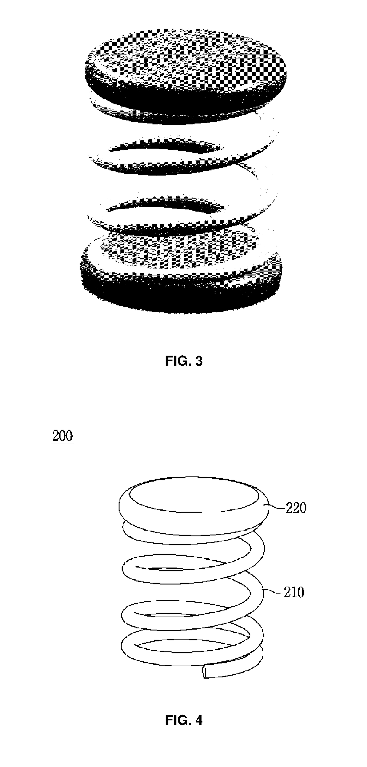
[0039]FIG. 1 illustrates an electric connecting terminal according to an embodiment of the present invention, FIG. 2 is a cross-sectional view that the electric connecting terminal of FIG. 1 is vertically cut, and FIG. 3 is a photo image for a real product.

[0040]An electric connecting terminal 100 is formed of a spring 110 of a metallic material having good elasticity and contacting parts 120 and 130 adhered to both ends of the spring 110 and having electric conductivity.

[0041]According to such a structure, the electric connecting terminal 100 is positioned between electric conductive objects, which oppose to each other, to elastically and electrically connect the objects due to compression and recovery of the spring 110.

[0042]As the electric conductive object, there may be a conductive pattern of a circuit board and a speaker terminal, and in this case, ...


PUM


Abstract

An electric connecting terminal, which is intervened between electric conductive objects to electrically connect the objects to each other, the electric connecting terminal including a spring of a metallic material, and a contact part having electric conductivity, which is formed by being adhered to at least one end of the spring and configured to electrically contact the object, wherein the contact part is formed by that the electric conductive material in which a liquid polymer resin is mixed with metallic power surrounds the end of the spring to be cured or flows into an end hole of the spring to be cured.

Description

REFERENCE TO RELATED APPLICATIONS[0001]This is a continuation of International Patent Application PCT / KR2016 / 003980 filed on Apr. 18, 2016, which designates the United States and claims priority of Korean Patent Application No. 10-2015-0111612 filed on Aug. 7, 2015, Korean Patent Application No. 10-2015-0124490 filed on Sep. 2, 2015, and Korean Patent Application No. 10-2015-0131270 filed on Sep. 16, 2015, the entire contents of which are incorporated herein by reference.FIELD OF THE INVENTION[0002]The present invention relates to an electric connecting terminal, and more particularly, to an electric connecting terminal which has a low height and simple structure to facilitate manufacturing, and of which a manufacturing cost is low and characteristics are easy to change.[0003]Furthermore, the present invention relates an electric connecting terminal of which an operating distance is long in comparison to the size and on which soldering is easily performed using vacuum pick-up.BACKGR...

Claims


Application Information

Patent Timeline
IPC IPC(8): H01R13/24H01R12/71
CPCH01R12/714H01R13/2421H01R13/03
Inventor KIM, SUN-KIPARK, KEE-HAN
Owner JOINSET
Why Eureka
Try Eureka