Syringe and fluid injection system with an orientation independent identification code

Inactive Publication Date: 2017-06-15
BAYER HEALTHCARE LLC
View PDF4 Cites 5 Cited by
  • Summary
  • Abstract
  • Description
  • Claims
  • Application Information

AI Technical Summary

Benefits of technology

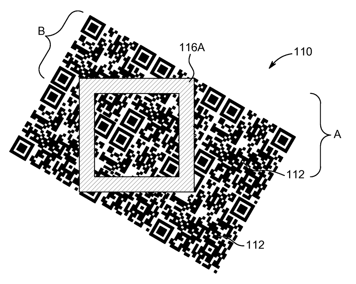
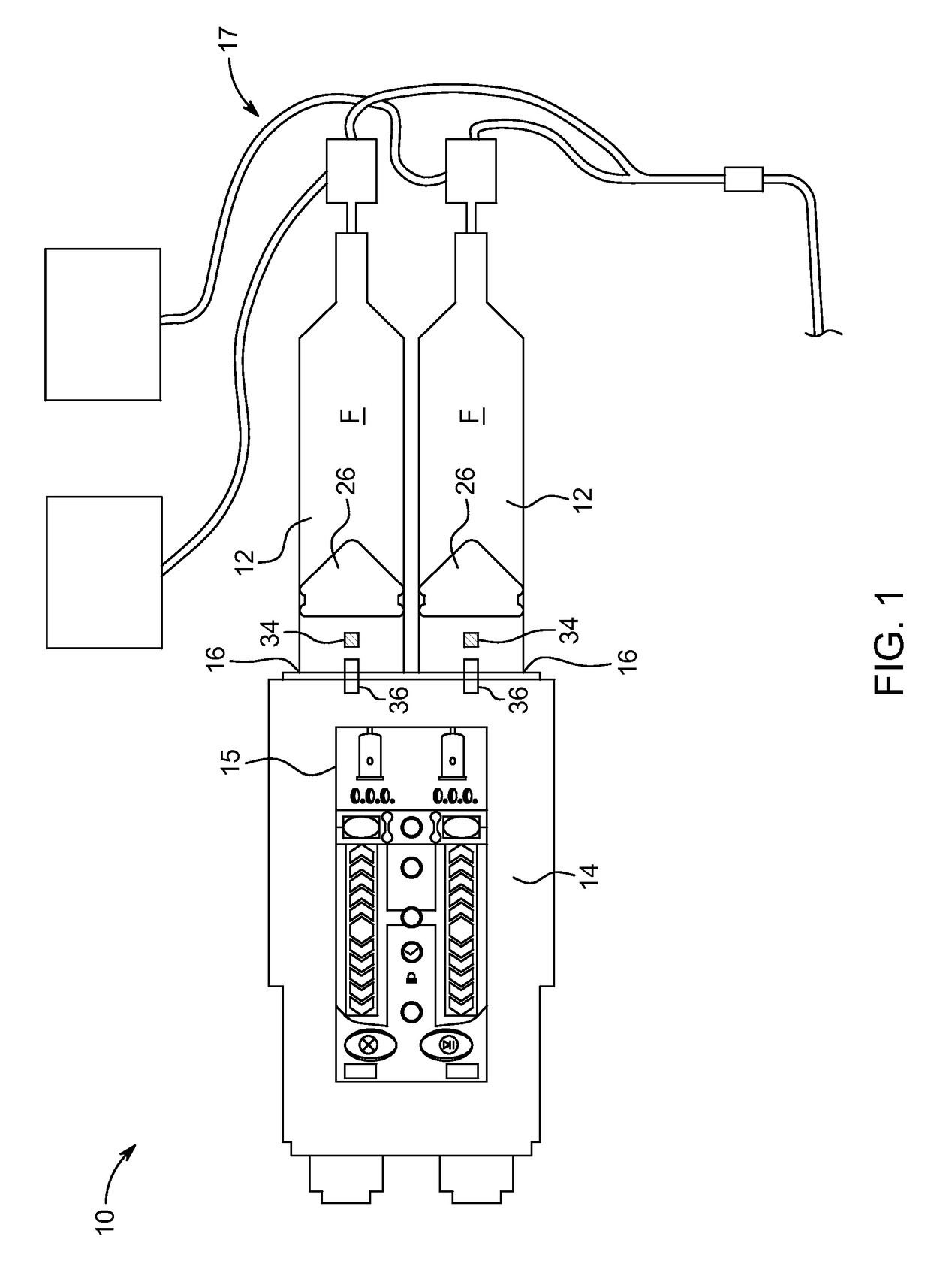
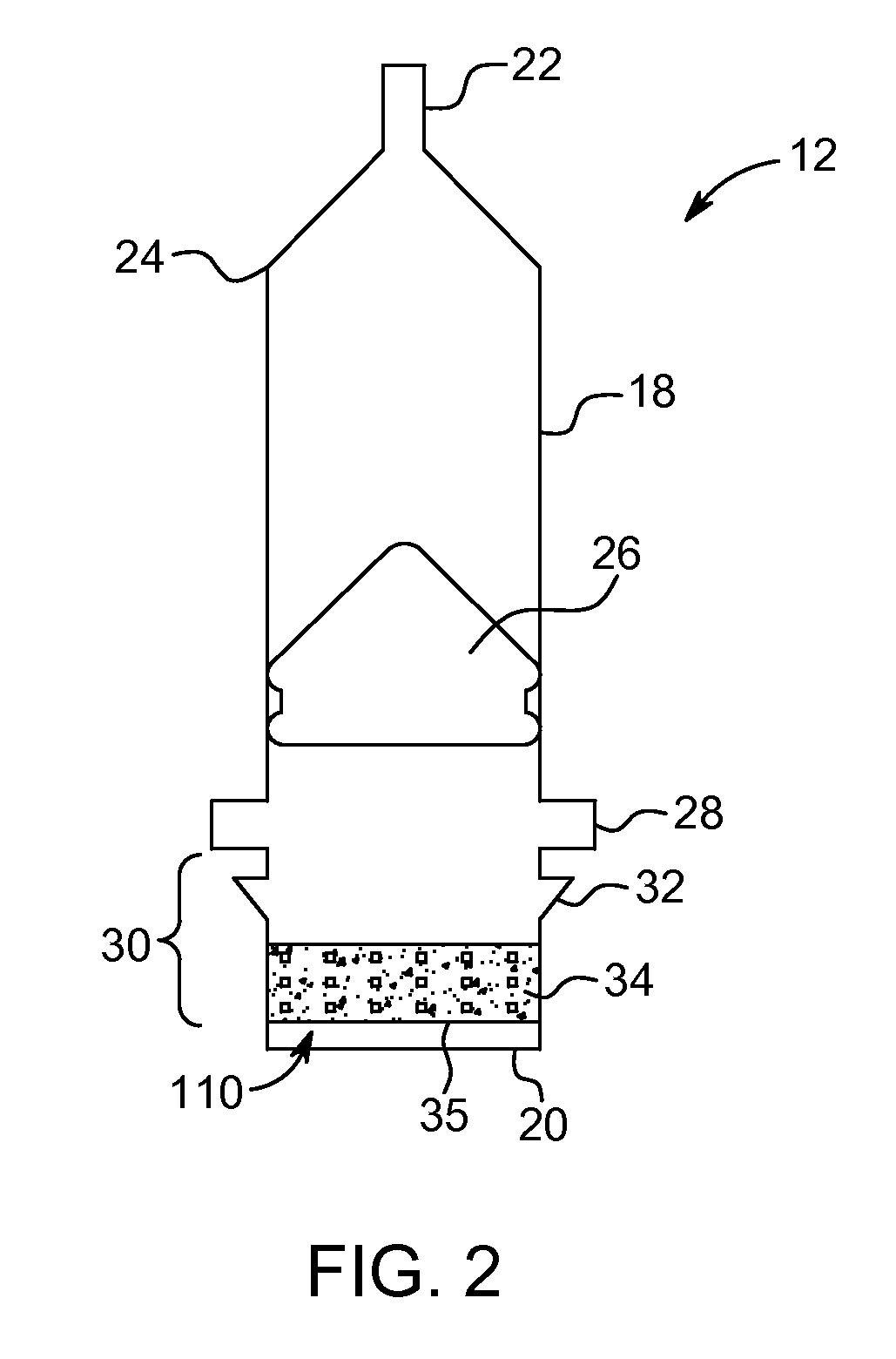
The patent describes an improved optical code or tag that can be applied to a syringe and piston to enable automatic syringe validation and injection control without requiring additional review, input, or data entry by the technician or operator. The code or tag is readable by a reader independent of the orientation of the syringe relative to the injector. The code or tag can include a plurality of barcode sections, straight markers, or a moiré pattern. The system includes a syringe with the code or tag, a fluid injector with a receiving port, a sensor, and a controller to extract identifying information from the code or tag and provide instructions for performing the injection. The code or tag can be read even when the syringe is rotated. The technical effect of this patent is to improve the efficiency and accuracy of syringe validation and injection control in a fluid injection system.

Problems solved by technology

Validation may also include confirming that the syringe assembly is genuine (e.g. to prevent counterfeiting, use of inferior or miss-fitting syringes that may result in improper mating between the syringe assembly and injector or may not have the required tolerances for a particular injection procedure, possibly resulting in malfunction during the procedure).
Including the various desired identifying information may be difficult given the amount of available surface area and aesthetic reasons.
For example, if the identifying information covers too much surface area on the syringe, it may impact the technician's ability to determine if the syringe has been properly filled.
This step of rotating the syringe to correctly align the sensor and tag increases time required to prepare the injector for an injection and can result in inaccuracies during the injection procedure.

Method used


Image

  • Syringe and fluid injection system with an orientation independent identification code
  • Syringe and fluid injection system with an orientation independent identification code
  • Syringe and fluid injection system with an orientation independent identification code

Examples


Embodiment Construction

[0032]For purposes of the description hereinafter, the terms “upper”, “lower”, “right”, “left”, “vertical”, “horizontal”, “top”, “bottom”, “lateral”, “longitudinal”, and derivatives thereof shall relate to the disclosure as it is oriented in the drawing figures. When used in relation to the syringe, the term “proximal” refers to the portion of the syringe nearest the injector, when the syringe is connected to the injector. The term “distal” refers to the portion of the syringe farthest away from the injector. It is to be understood, however, that the disclosure can assume alternative variations and step sequences, except where expressly specified to the contrary. It is also to be understood that the specific devices and processes illustrated in the attached drawings, and described in the following specification, are simply exemplary embodiments of the disclosure. Hence, specific dimensions and other physical characteristics related to the embodiments disclosed herein are not to be c...


PUM


Abstract

A syringe is provided including an orientation independent indicia that can be used to validate and determine information about the syringe, injection parameters, and / or fluid contained therein. The syringe includes a syringe barrel and an indicia located on a portion of the syringe containing or associated with identifying information about the syringe, one or more injection parameters of a fluid injector, or a fluid filled in the syringe barrel. The indicia is readable by a reader independent of an orientation of the syringe relative to the reader. A fluid injection system for providing fluid into a patient is also provided. The injection system includes the syringe having an orientation-independent indicia, an injector having at least one syringe receiving port for receiving the syringe, and a controller. The controller can be configured to obtain information from the indicia and provide instructions for performing injections to the injector, based on the information.

Description

CROSS REFERENCE TO RELATED APPLICATION[0001]The present application claims priority to U.S. Provisional Application No. 62 / 024,216 filed Jul. 14, 2014, the disclosure of which is incorporated by reference herein.BACKGROUND[0002]Field of the Technology[0003]The present disclosure relates generally to a syringe for containing a fluid for injection into a patient and, more specifically, to a syringe with an orientation independent indicia that can be used to validate and determine information about the syringe, injection parameters, and / or fluid contained therein.[0004]Description of Related Art[0005]In many medical, diagnostic, and therapeutic procedures, a medical practitioner, such as a physician, injects a patient with a medical fluid. In recent years, a number of injector-actuated syringes and powered injectors for pressurized injection of fluids, such as contrast media (often referred to simply as “contrast”), medicaments, or saline, have been developed for use in imaging procedu...

Claims


Application Information

Patent Timeline
IPC IPC(8): A61M5/31A61M5/00A61M5/168A61M5/145
CPCA61M5/3135A61M5/14546A61M5/007A61M2205/18A61M2205/60A61M2205/6072A61M5/16804A61M5/16827
Inventor UBER, III, ARTHUR E.PREM, EDWARD K.GOLDREIN, HOWELL TIMOTHY
Owner BAYER HEALTHCARE LLC
Why Eureka
Try Eureka