Cooling fan control method for vehicle

a technology of cooling fan and control method, which is applied in the direction of electrical apparatus contruction details, battery/fuel cell control arrangement, transportation and packaging, etc., can solve the problems of increasing the power consumption of the cooling fan, difficult to ensure the mounting space, and difficulty in ensuring the performance of the cooling module without increasing the capacity of the first and second cooling fans. , to achieve the effect of ensuring the performance of the cooling module without increasing the capacity of the first and second cooling fans

Active Publication Date: 2017-06-15
HYUNDAI MOTOR CO LTD
View PDF17 Cites 0 Cited by
  • Summary
  • Abstract
  • Description
  • Claims
  • Application Information

AI Technical Summary

Benefits of technology

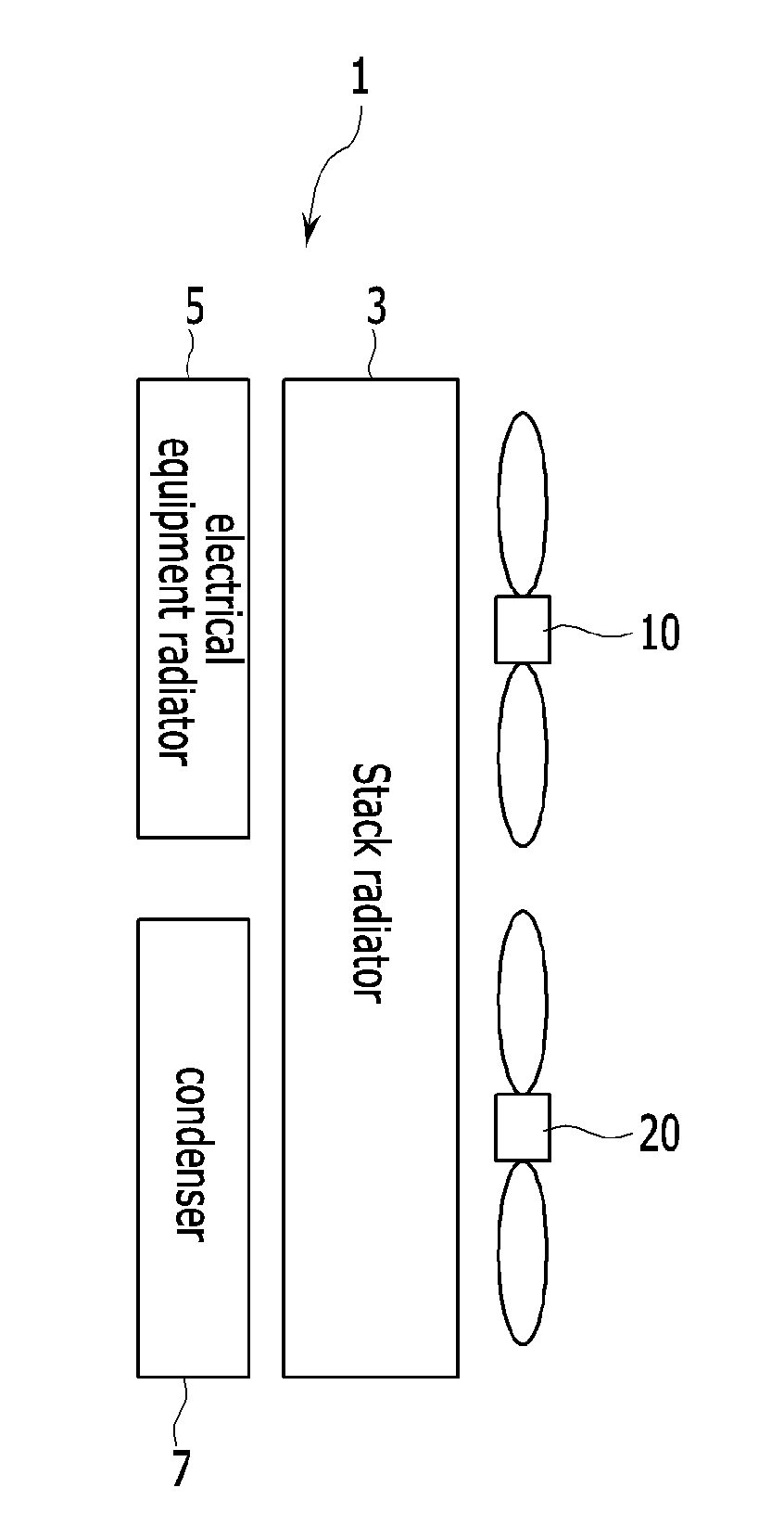
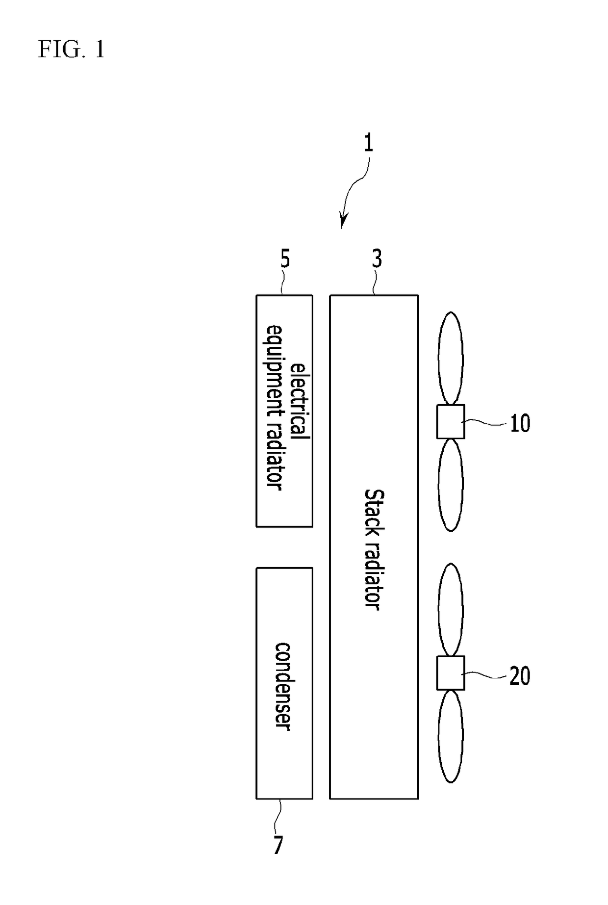
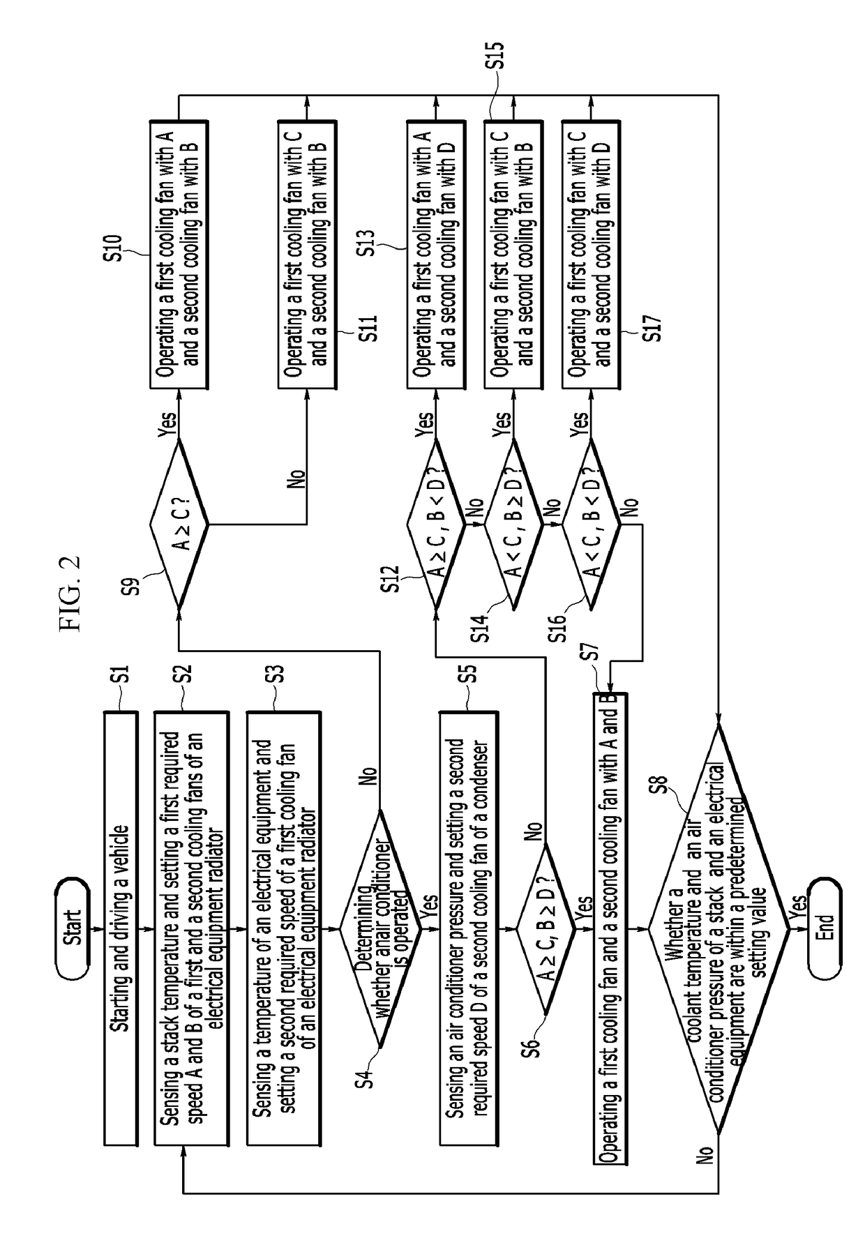
[0024]Accordingly, if the method of controlling the cooling fan for the vehicle according to an exemplary embodiment of the present invention configured as described above is applied, when operating the first and second cooling fans provided as a pair in the cooling module depending the running state of the vehicle in the electric vehicle according to the running state and the air conditioner operation, by independently controlling the operation speed of the first and second cooling fans by comparing the cooling fan required speed of each of the constituent elements, the unnecessary power consumption may be prevented by minimizing the power consumption of the first and second cooling fans such that the entire travel distance (i.e., range) of the vehicle may be increased.
[0025]Further, as it is possible to ensure the performance of the cooling module without increasing the capacity of the first and second cooling fans, a mounting characteristic of the cooling module may be improved in the limited mounting space, and the operability and operation efficiency of the stack, the electrical equipment, and the air conditioner system mounted in the vehicle may be improved.

Problems solved by technology

However, to ensure improved performance of the cooling module, capacity of the cooling fans must be increased and the cooling fans must be efficiently controlled, but it is difficult to ensure a mounting space in the limited engine compartment space, and as required cooling temperatures of the constituent elements are different, there is a drawback that it is difficult to control the cooling fans to meet the required cooling temperature of each of the constituent elements.
Also, among the required cooling temperatures of the constituent elements, when operating the cooling fans depending on a maximum cooling temperature, other constituent elements are unnecessary cooled, and the power consumption of the cooling fans is increased such that a maximum travel distance (i.e., range) of the vehicle is shortened.

Method used


Image

  • Cooling fan control method for vehicle
  • Cooling fan control method for vehicle
  • Cooling fan control method for vehicle

Examples


Embodiment Construction

[0028]It is understood that the term “vehicle” or “vehicular” or other similar term as used herein is inclusive of motor vehicles in general such as passenger automobiles including sports utility vehicles (SUV), buses, trucks, various commercial vehicles, watercraft including a variety of boats and ships, aircraft, and the like, and includes hybrid vehicles, electric vehicles, plug-in hybrid electric vehicles, hydrogen-powered vehicles and other alternative fuel vehicles (e.g. fuels derived from resources other than petroleum). As referred to herein, a hybrid vehicle is a vehicle that has two or more sources of power, for example both gasoline-powered and electric-powered vehicles.

[0029]The terminology used herein is for the purpose of describing particular embodiments only and is not intended to be limiting of the invention. As used herein, the singular forms “a,”“an” and “the” are intended to include the plural forms as well, unless the context clearly indicates otherwise. It will...


PUM


Abstract

A method of controlling cooling fans for a vehicle is configured to control operation speeds of first and second cooling fans depending on a running state and operation of an air conditioner of the vehicle in a cooling module including a stack radiator, an electrical equipment radiator disposed in front of the stack radiator, a condenser disposed in parallel with reference to a width direction of the electrical equipment radiator and the vehicle, and the first and second cooling fans being provided at positions respectively corresponding to the electrical equipment radiator and the condenser in the rear of the stack radiator, including: independently controlling operation of each cooling fan by comparing required speeds of the cooling fans of constituent elements when operating the cooling fans provided as a pair in the cooling module depending on the running state and the operation of the air conditioner in the electric vehicle.

Description

CROSS-REFERENCE TO RELATED APPLICATION[0001]This application claims under 35 U.S.C. §119(a) the benefit of Korean Patent Application No. 10-2015-0176323 filed in the Korean Intellectual Property Office on Dec. 10, 2015, the entire contents of which are incorporated herein by reference.BACKGROUND[0002](a) Field of the Invention[0003]The present invention relates to a method of controlling a cooling fan for a vehicle, more particularly, to a method of controlling a cooling fan in which power consumption is minimized by controlling operation of cooling fans provided as a pair in a cooling module in an electric vehicle depending on a vehicle state.[0004](b) Description of the Related Art[0005]In order to increase energy efficiency and reduce environmental pollution, development of an environmentally friendly vehicle that can substantially replace an internal combustion engine vehicle is desirable, and such an environmentally friendly vehicle can be classified into: an electric vehicle t...

Claims


Application Information

Patent Timeline
Patent Type & Authority Applications(United States)
IPC IPC(8): B60L11/18B60H1/00
CPCB60L11/1874B60H1/00878B60L11/1892B60L2240/36B60L58/33B60L58/26B60H1/32H05K7/20136B60L2240/545B60H2001/3269B60H2001/3248B60H1/00278B60H1/00471B60H1/00735B60H1/00828B60H2001/003Y02T10/70Y02T90/40
Inventor KIM, JAE YEONWON, SEUNG HYUN
Owner HYUNDAI MOTOR CO LTD
Why Eureka
Try Eureka