Wave energy converter

a converter and wave energy technology, applied in the direction of engine working fluid, machine/engine, sea energy generation, etc., can solve the problems of low energy conversion efficiency, failure of most r & ds, and failure to meet economical requirements, so as to achieve easy maintenance, reduce installation costs, and efficient and economical

Inactive Publication Date: 2017-06-15
OKINAWA INST OF SCI & TECH SCHOOL
View PDF21 Cites 3 Cited by
  • Summary
  • Abstract
  • Description
  • Claims
  • Application Information

AI Technical Summary

Benefits of technology

The present invention provides an efficient and economical wave energy converter that can be installed onshore, making maintenance easy. It is designed to be simple and intelligent and can easily handle changes in the environment. Additionally, it can effectively deal with extreme weather conditions for which it was designed, while also being low maintenance. Overall, this invention offers a cost-effective and environmentally friendly solution for converting wave energy.

Problems solved by technology

However, most of these R & Ds failed due to (1) low energy-conversion efficiency, (2) mechanical breakdown in storm conditions, (3) expensive installation, thereby not meeting economical requirements, and / or (4) unreliable design for operation for a long period of time.

Method used


Image

  • Wave energy converter
  • Wave energy converter
  • Wave energy converter

Examples


Embodiment Construction

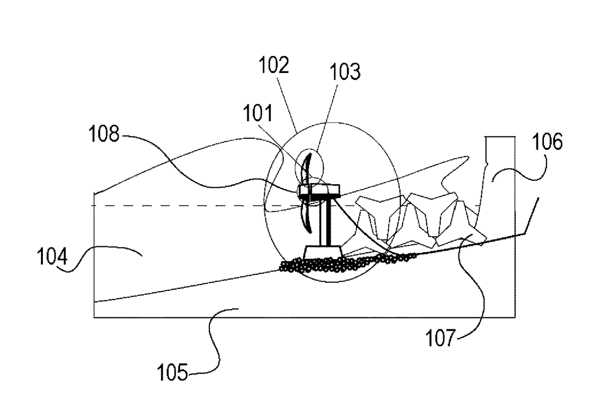
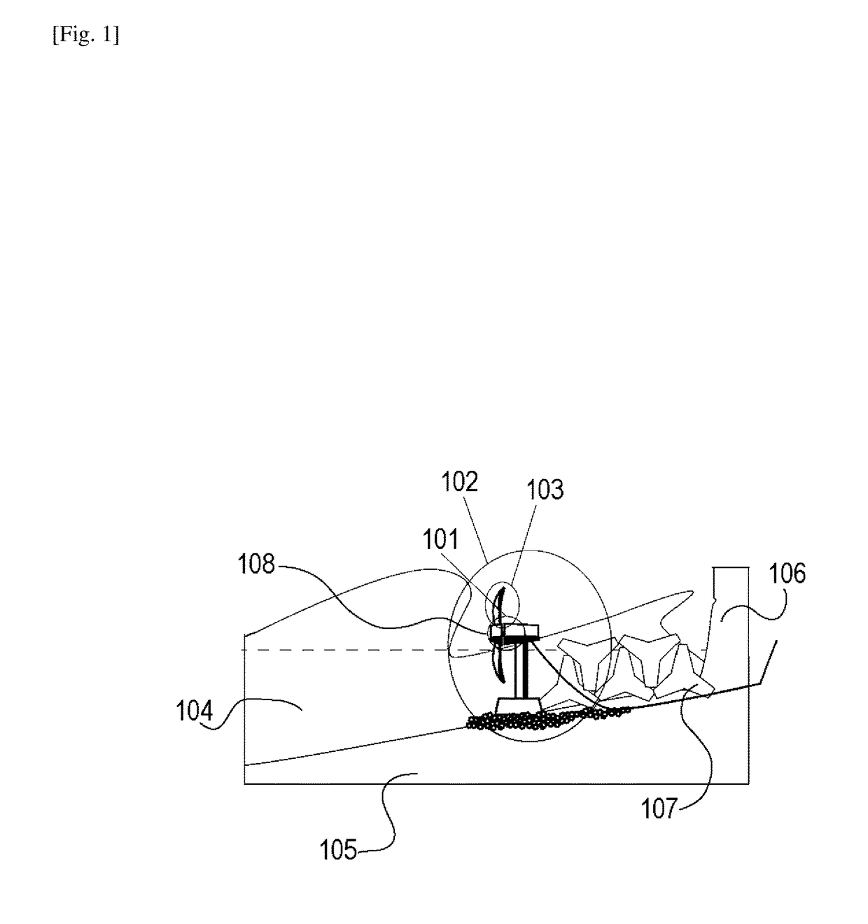
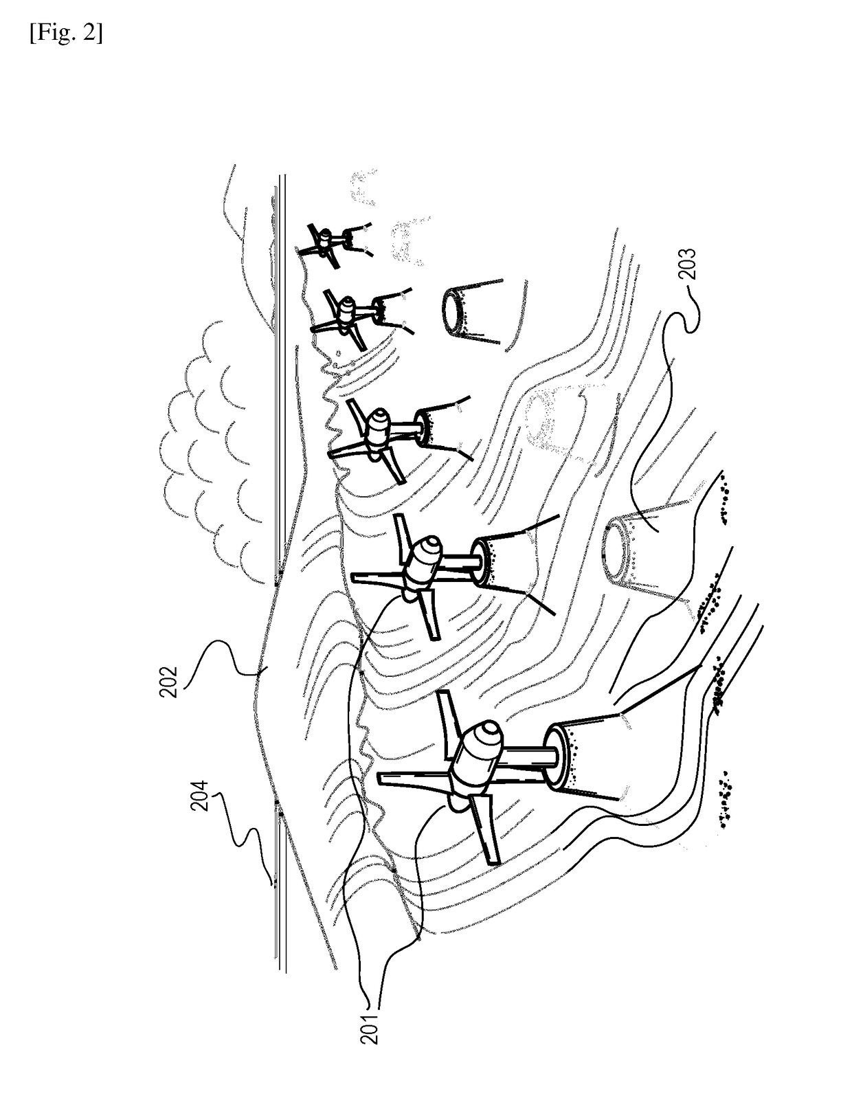
[0029]The present disclosure provides, in one aspect, a turbine with appropriately designed rotatable blades for Wave Energy Converter (WEC) to harness ocean energy to convert into electricity from flows of water in the onshore breaking waves. In some embodiments, a plurality of such turbines are installed near the shore so that forward and backward flows of the coastal waves near the coast line cause the rotations of the blades, thereby constituting a wave energy converter system that generates electricity. The ocean waves are normally mixed with vortex flows and air bubbles. Thus, the turbine has to run inside highly non-uniform multi-phase flows. When the ocean wave approaches to a shore, forward motion of wave crest becomes dominant. Because the sea floor acts as a drag force, the wave crest runs faster than the bottom, starting to break. In at least some of the embodiments disclosed herein, this fast running water slope has been used for surfing; here the present disclosure use...


PUM


Abstract

A wave energy converter system includes a plurality of wave energy converter units installed at or adjacent to a shoreline to receive water flows caused by ocean waves approaching the shoreline, each of the wave energy converter units including: a generator having a rotor shaft, the generator being configured to generate electricity in accordance with rotation of the rotor shaft; and a plurality of blades attached to the rotor shaft, the plurality of blades causing the rotor shaft of the generator to rotate in response to the water flows that impinge on the blades, thereby generating electricity; and a power conditioner installed onshore to receive the electricity generated by each of the plurality of wave energy converter units, the power conditioner providing consolidated electricity to an external power grid.

Description

TECHNICAL FIELD[0001]The present invention relates to a wave energy converter system, and more particularly to a wave energy converter system converting nearshore / onshore wave energy to electric power. This application hereby incorporates by reference United States Provisional Application No. 62 / 024,790, filed Jul. 15, 2014, in its entirety.BACKGROUND ART[0002]Numerous attempts have been made in recent years to utilize renewable energy on the earth as a supplement or alternative to the existing energy sources. In particular, ocean energy, such as offshore ocean wave energy, nearshore wave energy, and onshore wave energy, has been the subject to intensive research and development. A review of the wave energy technology can be found in a review article by Lopez, et al., for example, listed below as Non-Patent Literature (NPL) No. 1.[0003]As shown in NPL 1, for example, until recently, various types of the wave energy converters have been proposed and tested. Some of them use a floatin...

Claims


Application Information

Patent Timeline
Patent Type & Authority Applications(United States)
IPC IPC(8): F03B13/22F03B13/14
CPCF03B13/22F03B13/14F05B2240/91F05B2240/30F05B2240/40F05B2210/404F05B2240/311Y02E10/30
Inventor SHINTAKE, TSUMORU
Owner OKINAWA INST OF SCI & TECH SCHOOL
Why Eureka
Try Eureka