Concentric vertical pipe heat exchanger for drain water heat recovery

a heat exchanger and drain water technology, applied in the direction of indirect heat exchangers, stationary tubular conduit assemblies, lighting and heating apparatus, etc., can solve the problems of reducing performance, affecting reducing the efficiency of heat exchangers, so as to increase thermal contact conductance and heat transfer

Active Publication Date: 2017-06-15
MACKELVIE WINSTON
View PDF14 Cites 10 Cited by
  • Summary
  • Abstract
  • Description
  • Claims
  • Application Information

AI Technical Summary

Benefits of technology

[0024]In the conduit, a building's normal water pressure (or of another fluid) forces the inner sleeve tightly against the drainpipe. The pressure also thrusts the verti

Problems solved by technology

In addition, because it contains scum, tissues, particles, lumps, hair and the like, it cannot b

Method used


Image

  • Concentric vertical pipe heat exchanger for drain water heat recovery
  • Concentric vertical pipe heat exchanger for drain water heat recovery
  • Concentric vertical pipe heat exchanger for drain water heat recovery

Examples


Embodiment Construction

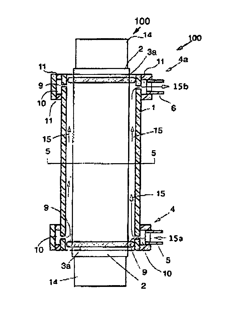
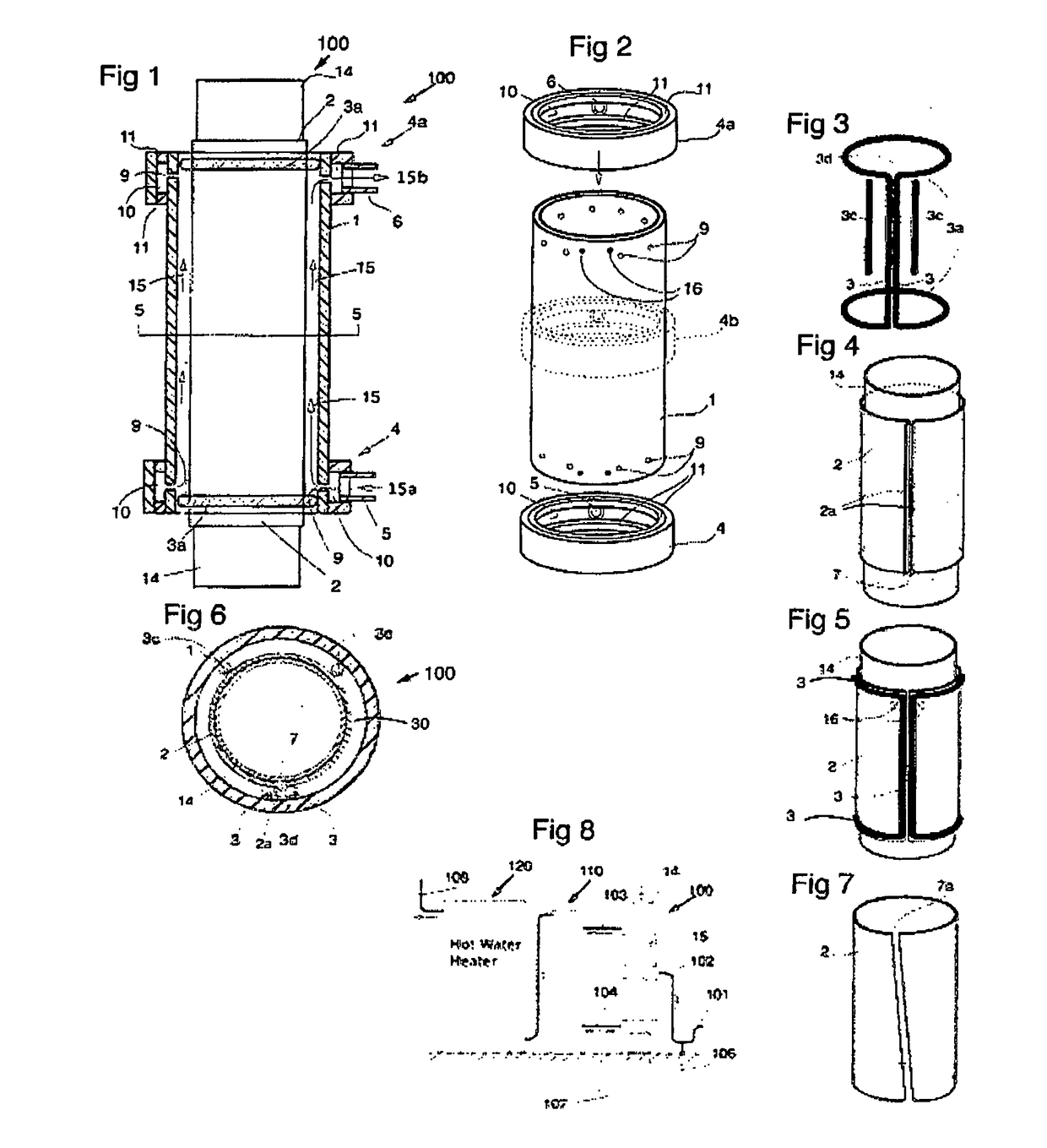
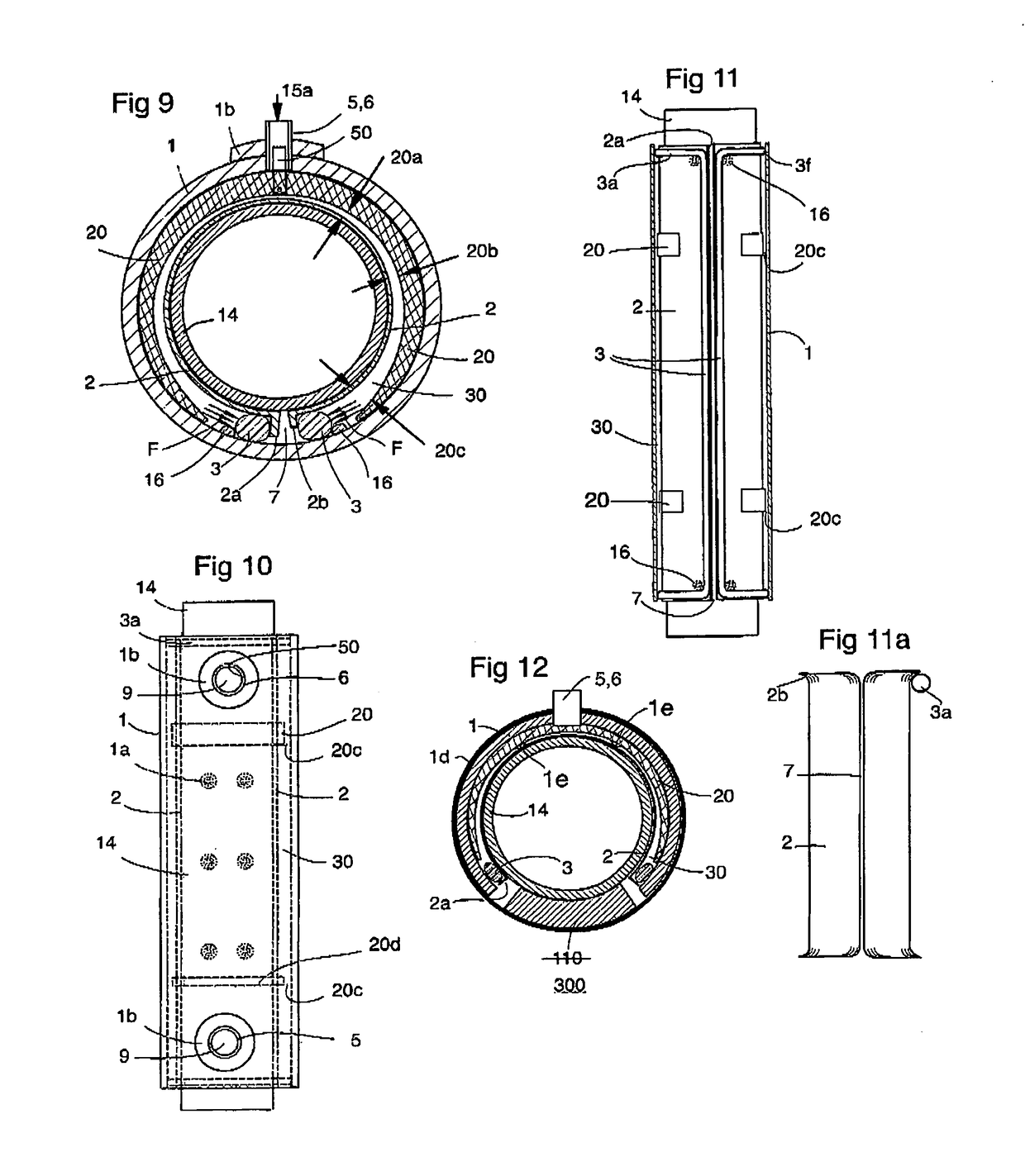
[0047]Referring to the drawings, drainpipe heat exchanger 104 has a central drainpipe 14, inner sleeve 2 with longitudinal (or vertical) extending opening or gap 7 and flanges 2a, 2b, outer cylinder 1, and continuous gasket (O-ring) 3, 3a. Preferably the drainpipe 14 is copper, the inner sleeve 2 is rolled sheet copper, and the outer cylinder 1 (a tube or cylinder) is rigid plastic such as PVC or ABS. The inner sleeve can be in a ‘soft’ anneal condition to allow it to conform intimately to any drainpipe surface irregularities.

[0048]In one embodiment external manifolds are used, an inlet manifold 4 (lower) and outlet manifold 4a (upper) that have inlet 5 and outlet 6 fittings. Internal circumferential flow channels 10 communicate with their respective apertures 9 which are spaced and / or sized according to their radial position: more an / or bigger holes farthest from fluid fittings, 5, 6. The inlet 5 and outlet 6 are positioned opposite gap 7.

[0049]FIGS. 2 and 8 show a central third ma...


PUM


Abstract

An outer plastic tube has water connections through the wall into an annular space defined by an O-ring spacer-gasket positioned between the wall and the perimeter margin of an inner cylinder rolled from a single-layer of sheet metal. A metal drainpipe with a removable bullet-shape at one end is forced through the cylinder to expand it and to thereby compress the gasket sealing the annular space. Thermal contact conductance is increased by the compressive force of water pressure. Water flow through the heat exchanger is both annular and turbulent to optimize heat transfer.

Description

[0001]This is a Continuation-in-Part of application / Control Ser. No. 13 / 986,583.FIELD OF THE INVENTION[0002]The present invention is in the field of heat exchangers and more particularly for immediate heat exchange between drainwater and a second fluid, such as fresh water, where both are flowing simultaneously. In such a scenario, each fluid changes temperature where the fresh water is either heated or cooled so that if further heating or cooling is required, the heat exchanger saves energy and money. As well, the final hot or cold temperature is reached more quickly which shortens recovery time.BACKGROUND OF THE INVENTION[0003]Drainwater heat recovery will be the example used in the following specification.[0004](By way of background: measured by weight or surface area, copper sheet is less expensive than copper tube. The term ‘thermal contact conductance’ is used for beat transfer between solids. The rate of heat transfer between solids is a function of: thermal conductivity; con...

Claims


Application Information

Patent Timeline
IPC IPC(8): F28F1/42F28F13/12
CPCF28F13/12F28F1/42F28F9/026F28F13/06F28D7/106F28D21/0012F28F1/003F28F2230/00Y02B30/56
Inventor MACKELVIE, WINSTON
Owner MACKELVIE WINSTON
Why Eureka
Try Eureka