
Regenerative variable frequency drive with auxiliary power supply

a variable frequency drive and auxiliary power supply technology, applied in the field of variable frequency drives, can solve the problems of complex installation and expense of dynamic braking resistors, the inability of three-phase active converters to convert the power from a single-phase ac source to charge the dc bus, and the availability of single-phase ac power in most residential and rural areas

Active Publication Date: 2017-06-15
PHASE TECH
View PDF4 Cites 11 Cited by
  • Summary
  • Abstract
  • Description
  • Claims
  • Application Information

AI Technical Summary

Benefits of technology

The patent describes a device that can convert single-phase AC power to variable frequency three-phase AC power or vice versa. It includes two inverters and an active converter. The device uses a hybrid voltage switching scheme to optimize the conversion process. The technical effect of this invention is the improved efficiency and precision of converting power between different forms.

Problems solved by technology

Dynamic braking resistors add complexity and expense to a variable frequency drive installation.
The known three-phase active converters cannot convert the power from a single-phase AC source to charge the DC bus.
However, only single phase AC power is available to most residential and rural areas.
Diode rectifier converters cannot directly boost the incoming 240 volts to 460 volts.
This distortion creates harmonic distortions that may affect other users on the grid.
The distortion also reduces the power factor.
Single-phase passive filters that meet IEEE-519 standards are expensive and not readily available.
Single-phase passive filters also have disadvantages such as resonance with the utility, large size and weight, and possible unsuitability for variable loads.

Method used


Image

  • Regenerative variable frequency drive with auxiliary power supply
  • Regenerative variable frequency drive with auxiliary power supply
  • Regenerative variable frequency drive with auxiliary power supply

Examples


Embodiment Construction

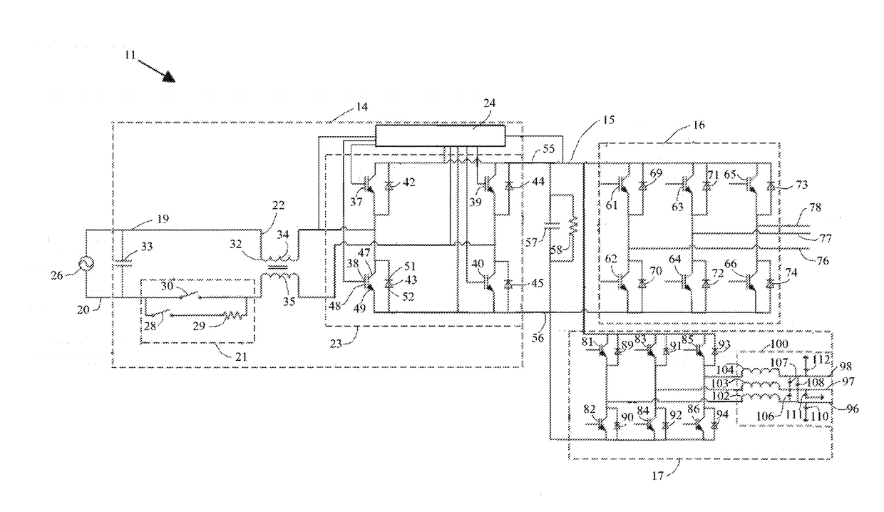
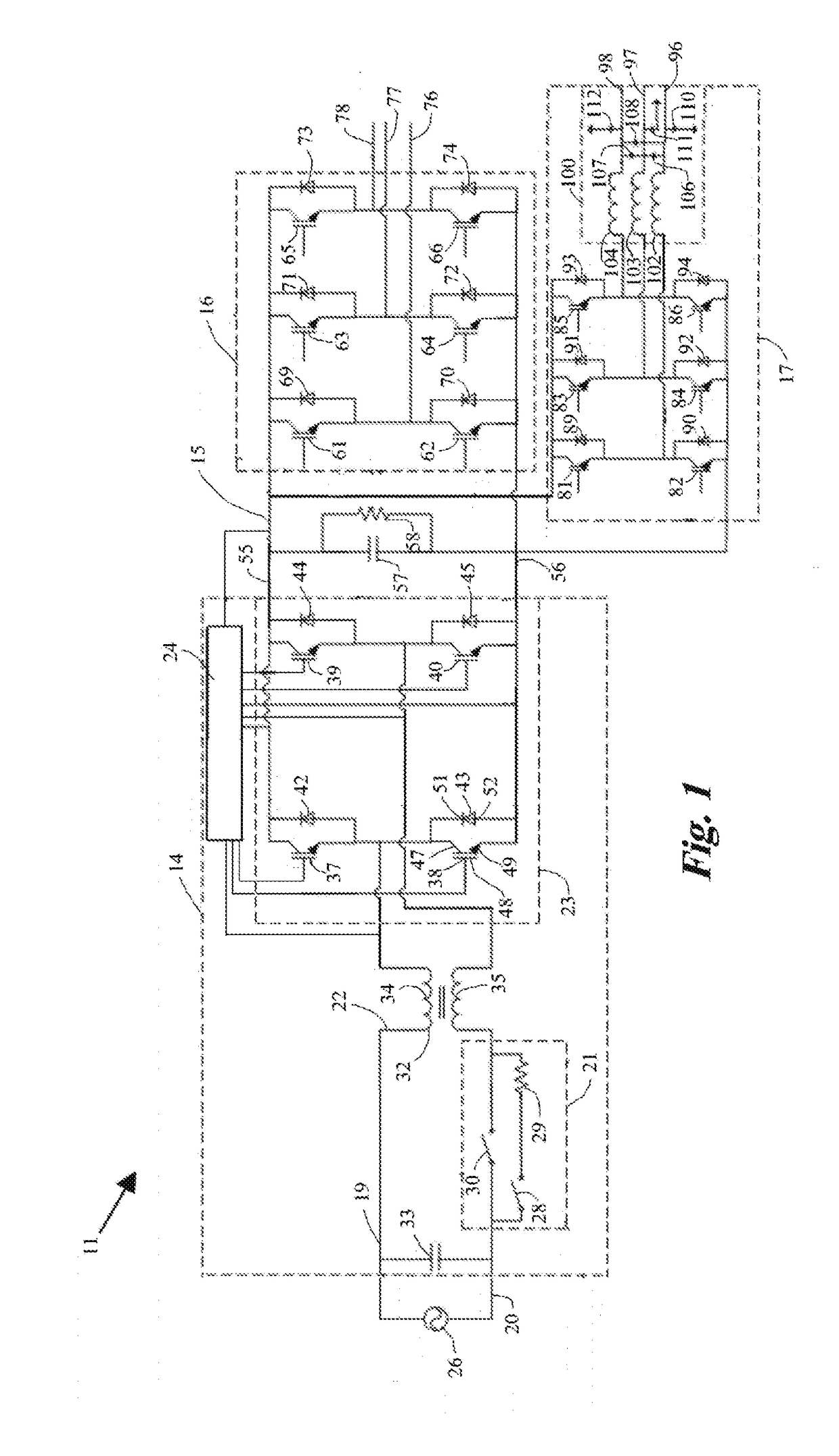
[0024]Referring to FIG. 1, a regenerative variable frequency drive 11, embodying the features of the present invention, includes an active converter 14, a DC bus 15 connect to the converter 14, and first and second inverters 16 and 17 connected to the DC bus 15. The converter 14 includes first and second input lines 19 and 20, a precharging circuit 21, an input filter 22, an active rectifier 23 and a controller 24. The first and second input lines 19 and 20 connect to a single phase AC source 26. Generally, the source 26 will be a utility power grid. In the United States, the source 26 will typically provide power at 240V at 60 Hz.

[0025]The precharging circuit 21 connects along the second input line 20 and includes a first switch 28 connected in series to a resistor 29, and a second switch 30 connected in parallel to the first switch 28 and the resistor 30. During startup of the drive 11, the first switch 28 is closed and the second switch 30 is open so that current passes through r...


PUM


Abstract

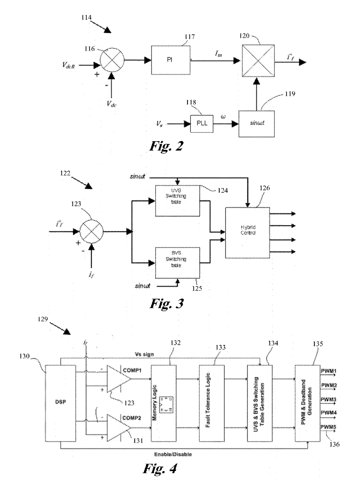
A regenerative variable frequency drive includes an active converter connected to a DC bus that is connected to a first inverter that converts DC power to variable frequency, three phase AC power, and variable frequency, three phase AC power to DC power, and to a second inverter that converts DC power to three phase AC sine wave power. The converter converts single phase AC power to DC power and DC power to single phase AC power, and maintains a selected voltage on the DC bus. The converter has an active rectifier and a controller that drives the rectifier with a pulse width modulation according to a hybrid voltage switching scheme that switches the rectifier according to a unipolar voltage switching scheme through most of each cycle and switches the rectifier according to a bipolar voltage switching scheme around each zero crossing.

Description

TECHNICAL FIELD[0001]The present invention relates to variable frequency drives and more particularly to a regenerative variable frequency drive with an active converter that converts with a hybrid voltage switching method from single-phase AC input to DC, and from DC to three-phase variable frequency AC output and to three-phase sine wave AC output.BACKGROUND ART[0002]A variable frequency drive controls the speed and torque of an alternating current (AC) motor by varying the input frequency and voltage. Three-phase motors provide higher mechanical efficiency, higher power factor and less torque ripple than single-phase motors and are therefore a more desirable choice. Variable frequency drives in the past have generally included a diode rectifier, that converts AC power to direct current (DC) power, connected through a DC bus to an inverter that supplies three phase, variable frequency AC power to a three-phase motor.[0003]When a motor turns faster than the speed designated by the ...

Claims


Application Information

Patent Timeline
IPC IPC(8): H02M5/458
CPCH02M5/458H02M1/4233H02M5/4585H02M7/219H02M1/008H02M1/088Y02B70/10H02M1/0006
Inventor MEDAGAM, PEDA V.PETTYJOHN, THEODORE CLIFTONYANG, JACK
Owner PHASE TECH
Learn More