Chassis structure for industrial uninterruptible power supply system

a power supply system and chassis technology, applied in emergency power supply arrangements, casings/cabinets/drawers, electric apparatus casings/cabinets/drawers, etc., can solve the problems of inducing voltage reduction or power outage to power users, increasing the complexity of the functions of information and communication of data centers and equipment rooms, and huge data processing by this equipment. , to achieve the effect of improving heat dissipation performan

Active Publication Date: 2017-06-15
VOLTRONIC POWER TECH CORP
View PDF1 Cites 29 Cited by
  • Summary
  • Abstract
  • Description
  • Claims
  • Application Information

AI Technical Summary

Benefits of technology

[0011]The main object of the instant disclosure is to provide a chassis structure for an industrial uninterruptable power supply system having improved heat dissipation performance, while ensuring the protection property of the chassis to prevent external contaminants from entering the chassis and causing short circuit or damage of the circuit components disposed in the chassis.
[0020]The advantage of the instant disclosure is that the instant disclosure can improve the operation stability, reliability and safety of the uninterruptable power supply system while ensuring the protective and heat dissipation performance thereof.

Problems solved by technology

However, the existing public power supply systems usually are affected by broken wires and short circuits in the wiring transmission-distribution, thereby inducing voltage reduction or power outage to the power users.
The complexity of the functions of the information and communication of the data centers and equipment rooms are increased and the data processed by this equipment is huge.
Therefore, there is a dilemma in the design of the conventional uninterruptable power supply system.
In addition, the installing position of the inner circuit components in the chassis of the conventional uninterruptable power supply systems is not optimized and hence, when an error occurs, the malfunctioning components are usually disposed at the left and right side, or even at the rear side of the chassis.
Based on the above, the heat dissipation property of the chassis of the conventional industrial uninterruptable power supply system and the protection thereof is not good.

Method used


Image

  • Chassis structure for industrial uninterruptible power supply system
  • Chassis structure for industrial uninterruptible power supply system
  • Chassis structure for industrial uninterruptible power supply system

Examples


Embodiment Construction

[0037]Reference will now be made in detail to the exemplary embodiments of the instant disclosure, examples of which are illustrated in the accompanying drawings. Wherever possible, the same reference numbers are used in the drawings and the description to refer to the same or like parts.

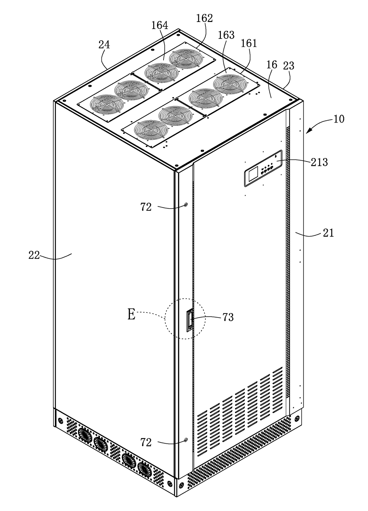
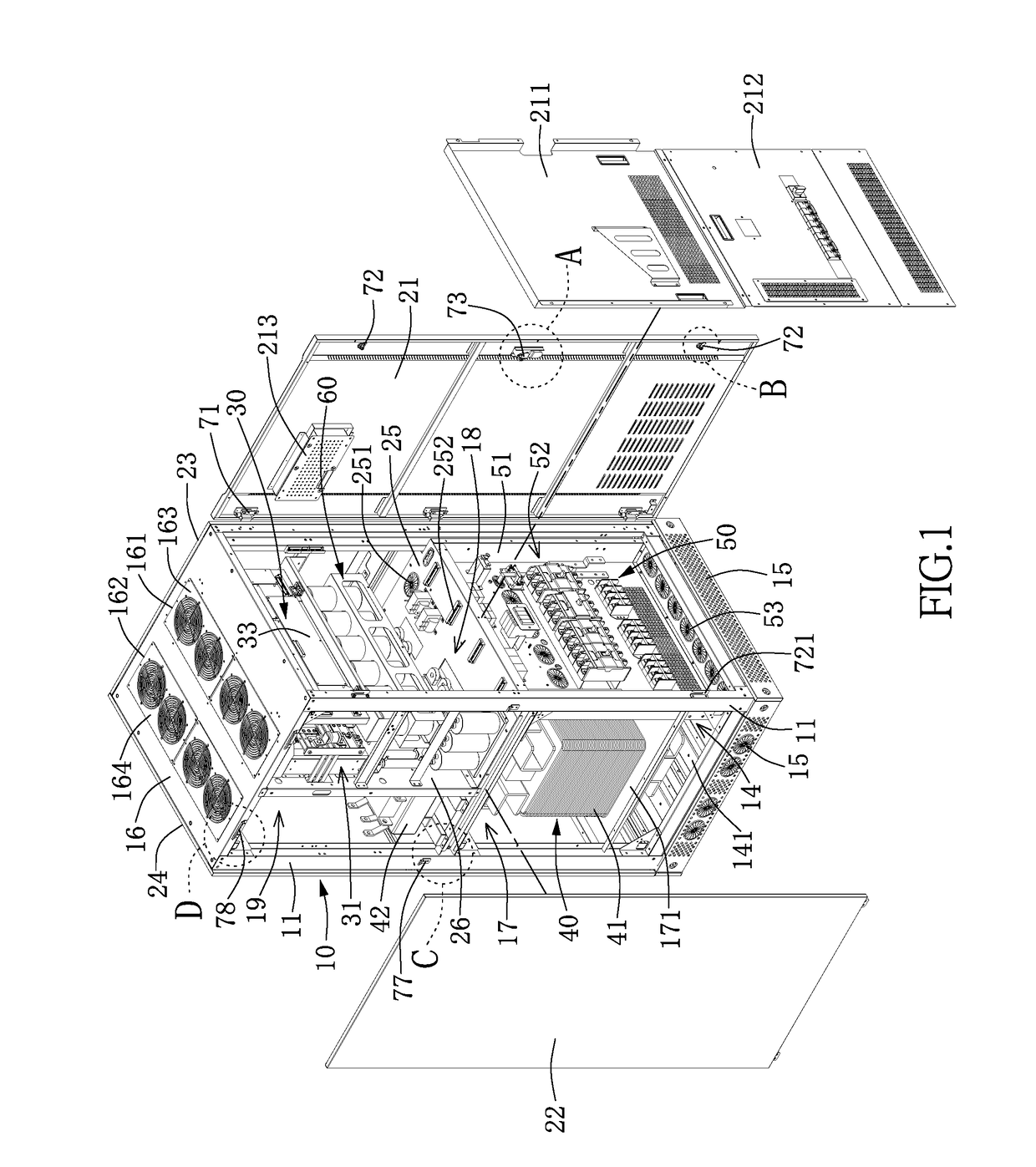
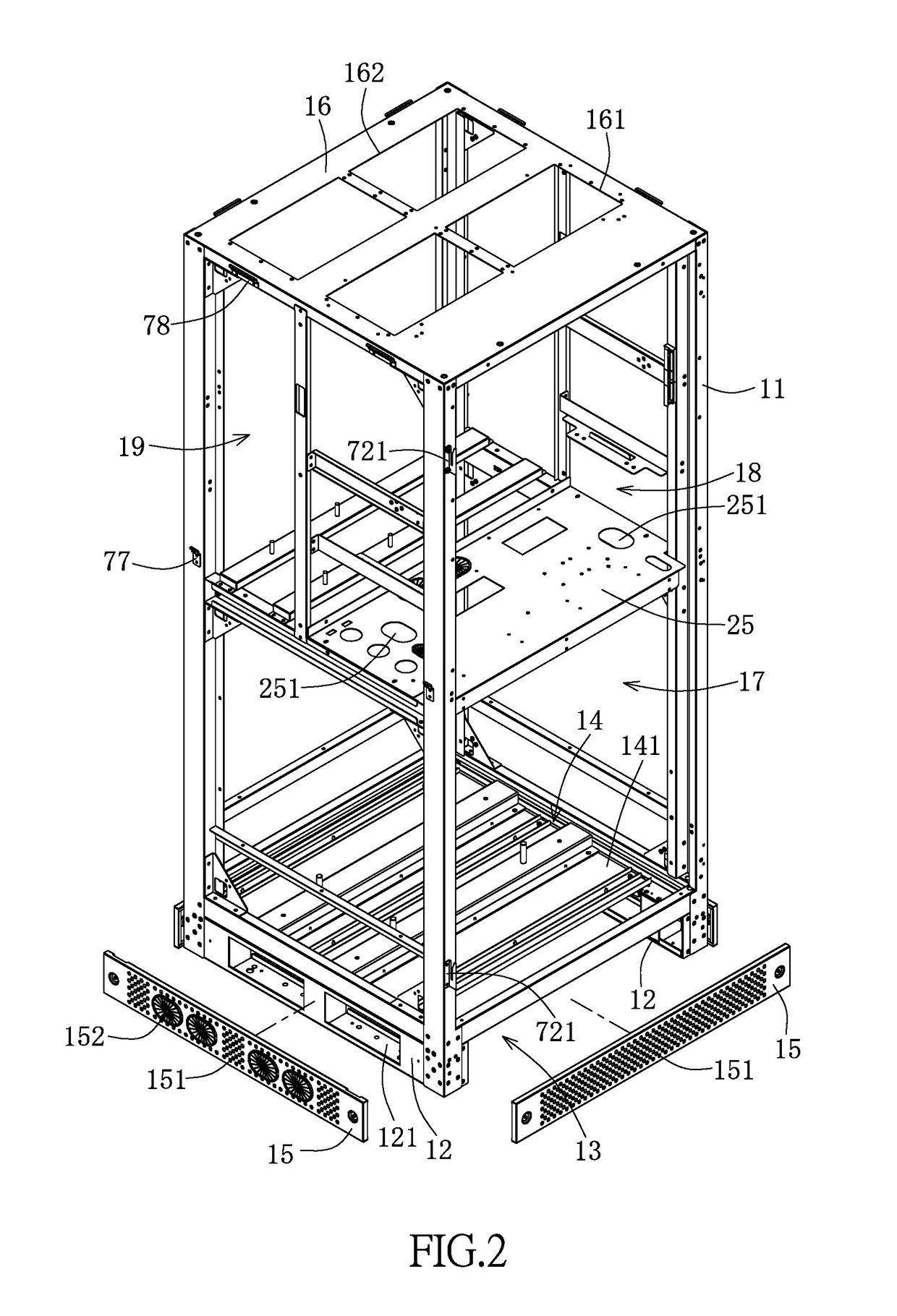
[0038]As shown in FIG. 1 to FIG. 4, the chassis structure for an industrial uninterruptable power supply system mainly comprises a chassis 10, which is a vertical tower chassis. The chassis 10 has a frame 11 and a front side panel 21, a left side panel 22, a right side panel 23, a rear side panel 24 and a top panel 16 installed on the frame 11.

[0039]As shown in FIG. 1, the frame 11 is a square frame formed by a plurality of rods. The front side panel 21 is disposed at the front side surface of the frame 11 and has a display panel 213 disposed thereon for displaying the status for the user to operate the uninterruptible power supply system. The front side surface of the frame 11 may further comprise ...


PUM


Abstract

The instant disclosure relates to a chassis structure for industrial uninterruptible power supply system including: a chassis having a frame and a front side panel, left side panel, right side panel, rear side panel and top panel installed on the frame; the chassis has a plurality of spacer on the bottom thereof for lifting the chassis from the ground for a distance to forming a gas-intake space; a plurality of protective plates disposed around the gas-intake space, each protective plate has a plurality of gas-intake hole; a bottom plate structure disposed between the bottom of the chassis and the gas-intake space and has at least a gas-intake gap; at least a venting hole disposed on the top panel of the chassis, each venting hole has at least an exhaust fan for outputting a gas from the chassis.

Description

BACKGROUND[0001]1. Technical Field[0002]The instant disclosure relates to a chassis structure for uninterruptible power supply system, in particular, to a chassis structure for large-scale industrial uninterruptible power supply system.[0003]2. Description of Related Art[0004]A large amount of computer and automatic equipment is employed in the information equipment room in the network or communication industries, the control center of the public traffic facilities such as the metro, high speed railway and highway, and the control center of the hospitals and productive factories. During the operation of this information and electronic equipment, stable and uninterruptible power supply is a basic requirement for running normally. However, the existing public power supply systems usually are affected by broken wires and short circuits in the wiring transmission-distribution, thereby inducing voltage reduction or power outage to the power users.[0005]The existing uninterruptible power ...

Claims


Application Information

Patent Timeline
Patent Type & Authority Applications(United States)
IPC IPC(8): H05K7/20H05K5/02H02J9/06H05K7/14
CPCH05K7/20909H05K7/20154H02J9/06H05K5/0217H05K7/14H05K7/20572H05K7/14325H05K7/1432
Inventor YU, TUNG-CHENWAN, XIAO-BOHSIEH, JUOR-MING
Owner VOLTRONIC POWER TECH CORP
Why Eureka
Try Eureka