
Weight loading system for fitness equipments

a technology for fitness equipment and weight loading, applied in the field of fitness equipment, can solve the problems of large frame and heavy total weight, difficult for such devices to enter the household market, inconvenient movement and installation, etc., and achieve the effects of increasing load capacity, simplifying structure, and large load capacity

Active Publication Date: 2017-06-22
NINGBO JADA HEALTH TECH
View PDF4 Cites 35 Cited by
  • Summary
  • Abstract
  • Description
  • Claims
  • Application Information

AI Technical Summary

Benefits of technology

The present invention is a weight loading system for fitness equipment that uses a simple and lightweight permanent magnet brushless DC motor to replace the traditional block as a weight. This system has a stepless control effect and can adjust the force of the weight through the use of electromagnetism. The motor has a large load capacity and does not require an additional reducer, which simplifies the structure and lowers the cost. The system can also control the rotating speed to overcome problems of the prior art, such as dropping the clump weight or damaging the equipment while loosening the power driving mechanism. The motor has a wheel hub structure that allows for easy and controllable speed and force during the stretching or retracting process.

Problems solved by technology

The fitness equipment has a large frame and a heavy total weight and occupies much space, and thus it is inconvenient to move and install.
Besides the places such as gym, it is difficult for such device to enter into the household market.
1. Since the output end of the motor is the main shaft, the torque is small, and the rotating speed is high, therefore the reducer is installed to reduce the speed and increase the torque. As a result, the structure and operation become very complicated and cumbersome, and incur a high cost.
2. The linkage mechanism and operating rod of the mechanical structure are adopted to transmit the torque increased by the reducer to a driving mechanism for the force operation of a human body, so that both structure and operation are very complicated and the cost is even higher.

Method used


Image

  • Weight loading system for fitness equipments
  • Weight loading system for fitness equipments
  • Weight loading system for fitness equipments

Examples


Embodiment Construction

[0034]The above and other objects, features and advantages of this disclosure will become apparent from the following detailed description taken with the accompanying drawings.

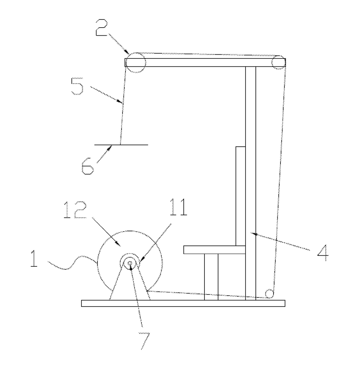
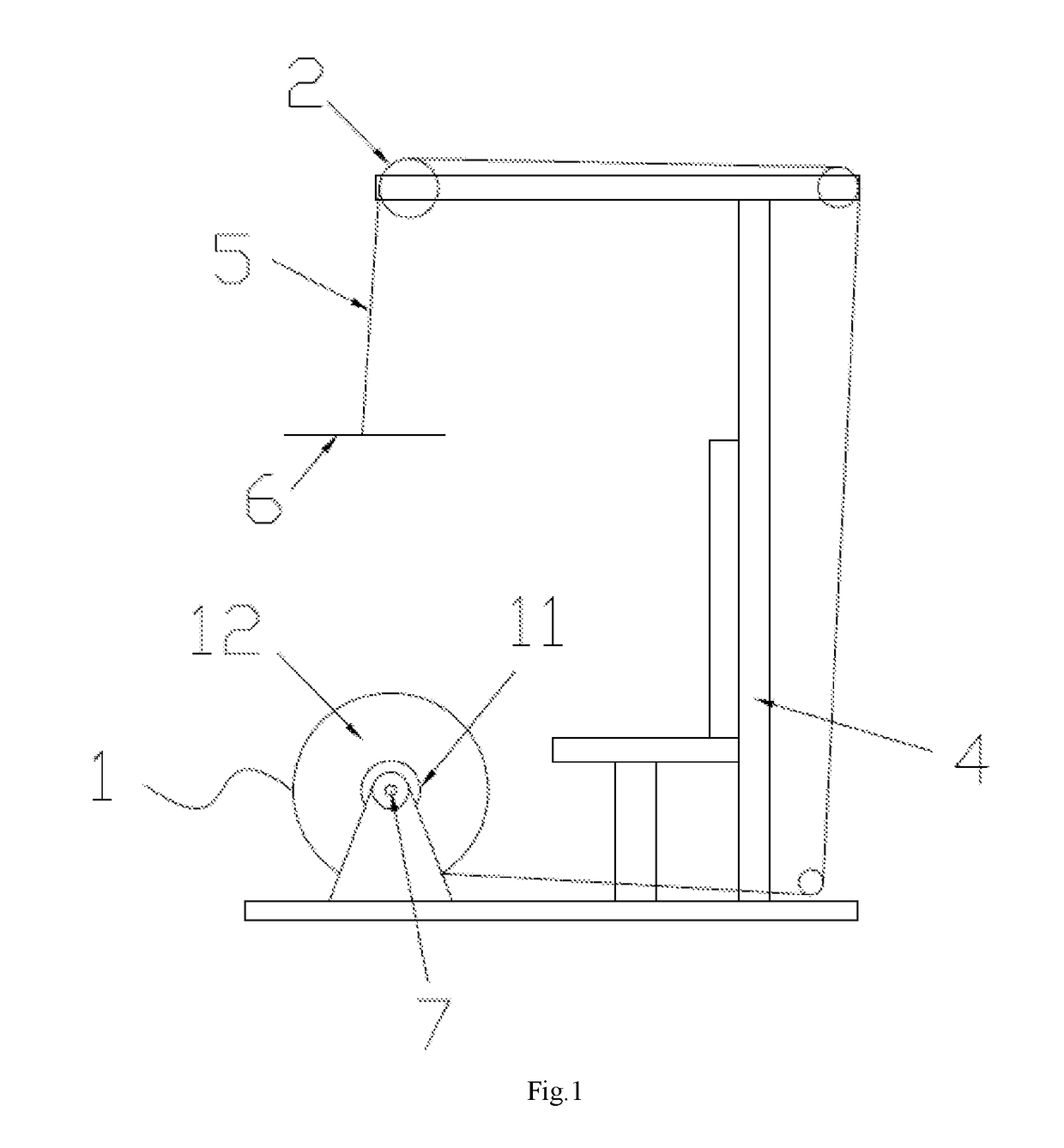
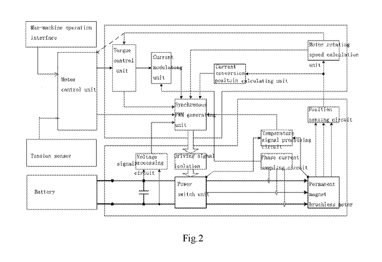
[0035]With reference to FIGS. 1 and 3 for a fitness equipment provided for training a user's back, and the fitness equipment comprises a fitness equipment support (4), a rally rope (5), a motor (1), a motor driving module and a motor control unit; the motor (1) is a permanent magnet brushless DC motor with an external rotor structure, and specifically a wheel hub type motor, and the motor includes a stator (11) mounted onto the fitness equipment support (4) and an external rotor (12) sheathed on the stator (11) and rotatable with respect to the stator (11), and the rally rope (5) is wound around the external rotor (12) of the motor (1), and an end of the rally rope (5) is coupled to the external rotor of the motor (1), and the other end of the rally rope (5) is coupled to the power driving mechanism (6) of the...


PUM


Abstract

A weight loading system for fitness equipments includes a fitness equipment support, a rally rope, a motor, a motor driving and a motor control unit. The motor is a permanent magnet brushless DC motor with an external rotor structure, and the motor includes a stator mounted onto the fitness equipment support and an external rotor sheathed on the stator and rotatable with respect to the stator, and the rally rope is wound around the external rotor of the motor, and an end of the rally rope is coupled to the external rotor of the motor, and the other end of the rally rope is coupled to the power driving mechanism of the fitness equipment; the power driving mechanism is provided for driving the external rotor of the motor through the rally rope to rotate and generate a rally, and the motor control unit controls the motor to rotate in an opposite direction through the motor driving module, so as to produce a load force opposite to the rally. The weight loading system for fitness equipments structure is simple, lightweight, and achieves the effect of a stepless weight control.

Description

FIELD OF INVENTION[0001]The present invention relates to the field of fitness equipments, in particular to a weight loading system for fitness equipments.BACKGROUND OF INVENTION[0002]1. Description of the Related Art[0003]In general, a conventional fitness equipment uses an iron block as a weight load. As disclosed in P.R.C. Pat. Publication No. CN 204380069 U, a load rally device has a main function of loading a weight by selecting a clump weight with an appropriate weight according to a user's force, but such device has the following drawbacks. The fitness equipment has a large frame and a heavy total weight and occupies much space, and thus it is inconvenient to move and install. Besides the places such as gym, it is difficult for such device to enter into the household market.[0004]Therefore, another conventional fitness equipment as disclosed in P.R.C. Pat. Publication No. CN 202699935U is introduced into the market, and such fitness equipment relates to a muscle training contr...

Claims


Application Information

Patent Timeline
IPC IPC(8): A63B24/00A63B21/00A63B21/22A63B21/005
CPCA63B24/0087A63B21/0058A63B2220/35A63B21/22A63B21/4035A63B21/154A63B23/0233A63B23/03525A63B23/1209A63B2022/0079A63B2220/10A63B2220/34A63B2220/36A63B2220/51A63B21/4043H02P6/00H02P2207/05H02P6/32
Inventor LU, WEIDONG
Owner NINGBO JADA HEALTH TECH
Learn More