A breaker device for interrupting current on a transmission line

a technology of interrupting current and transmission line, which is applied in the direction of electronic switching, emergency protective arrangements for limiting excess voltage/current, pulse technique, etc., can solve the problems of extremely short turn-off time of components and use of expensive components

Active Publication Date: 2017-06-22
GENERAL ELECTRIC TECH GMBH
View PDF1 Cites 6 Cited by
  • Summary
  • Abstract
  • Description
  • Claims
  • Application Information

AI Technical Summary

Benefits of technology

[0029]The breaker device of the invention does not include a timer sub-branch. An advantage of the invention is to reduce the size and the cost of the breaker device and to increase its reliability.
[0030]The interrupted current flowing in the main branch may be the nominal current or some other current, e.g. a current that is greater than the nominal current and that results from the appearance of a fault in the electrical equipment to which the breaker device belongs.BRIEF DESCRIPTION OF THE FIGURES
[0031]Other characteristics and advantages of the invention appear on reading the description given below with reference to the accompanying figures, in which:
[0032]FIGS. 1A and 1B show a first variant of a breaker device in a first

Problems solved by technology

It is necessary for the turn-off time of the components to be extremely short.
This technical requirement results in using components that are expensive.

Method used


Image

  • A breaker device for interrupting current on a transmission line
  • A breaker device for interrupting current on a transmission line
  • A breaker device for interrupting current on a transmission line

Examples


first embodiment

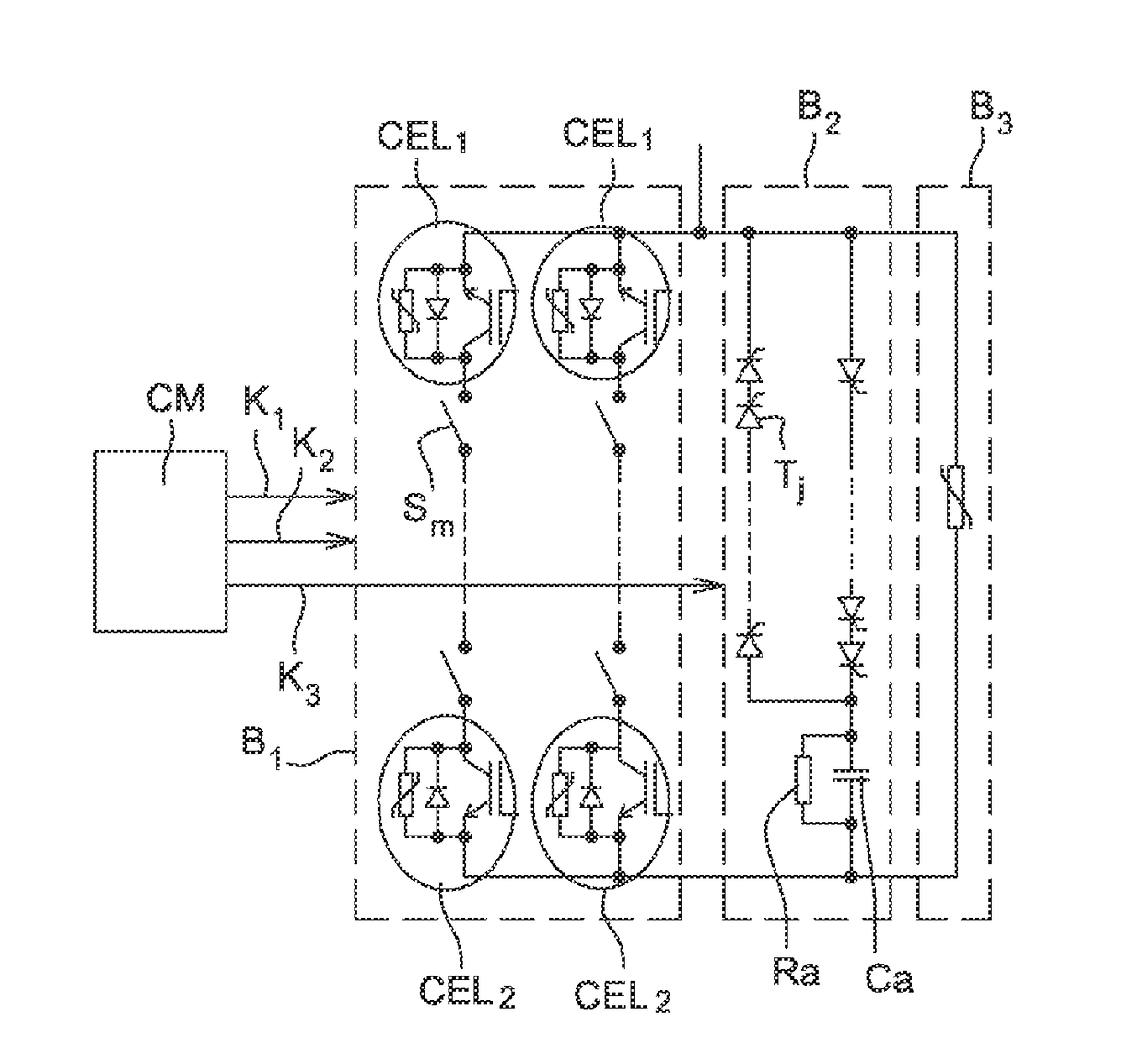
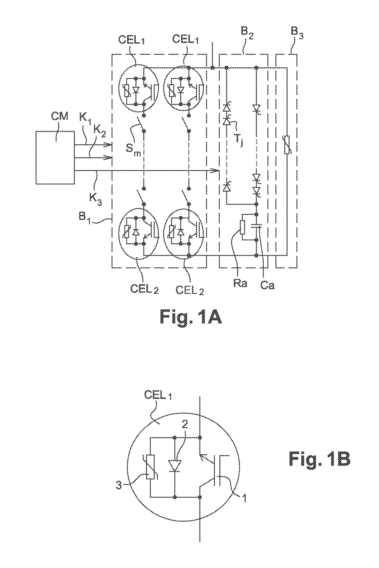
[0041]FIGS. 1A and 1B show a first variant of a breaker device in the invention.

[0042]FIG. 1A shows the essential electrical elements that constitute the breaker device in its entirety, and FIG. 1B shows a view of a detail of one of the elements shown in FIG. 1A.

[0043]The breaker device comprises three branches in parallel B1, B2, B3 and a control circuit CM. The branches are composed of a main branch B1 in which the current to be interrupted flows, an auxiliary branch B2, and a branch B3 that is constituted by a lightning arrester.

[0044]By way of non-limiting example, the main branch B1 comprises two parallel sub-branches, each sub-branch comprising at least one mechanical interrupter / disconnector Sm and two semi-conductor breaker cells CEL1, CEL2. Preferably, each breaker cell CELi (i=1, 2) is placed at a respective end of the sub-branch, and the mechanical disconnector(s) is / are placed between the breaker cells. By way of example, each semi-conductor breaker cell CELi (i=1, 2) co...

second embodiment

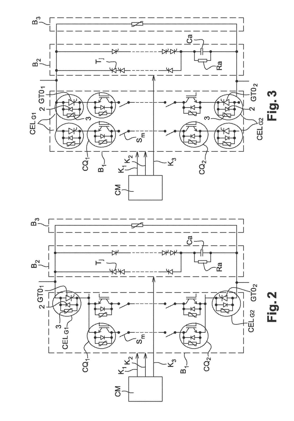
[0079]FIG. 6 shows a breaker device in the invention.

[0080]The second embodiment of the invention corresponds to an improvement of the first variant of the first embodiment.

[0081]In certain applications, the breaking capacity of IGBTs is not sufficient. In order to deal with this insufficiency, the second embodiment of the invention makes provision for the presence of at least one additional breaker cell CELCi (i=1, 2) in parallel with at least one breaker cell provided with at least one IGBT, which additional breaker cell has breaking capacity that is greater than the breaking capacity of the initial breaker cell CELi provided with the IGBT.

[0082]By way of example, a breaker cell CELCi (i=1, 2) is constituted by at least one GTO thyristor 4 connected in parallel with control electronics 5. In a first variant of the second embodiment of the invention, the control electronics 5 include at least one voltage limiter that is dimensioned so as to conduct the current for interrupting by t...


PUM


Abstract

A breaker device for interrupting current flowing on a transmission line, the device comprising three electrical branches (B1, B2, B3) connected in parallel, including a main branch (B1) in which the current to be interrupted flows and an auxiliary branch (B2), the main branch comprising at least one semi-conductor breaker cell (CEL1) connected in series with at least one mechanical interrupter / disconnector (Sm), the auxiliary branch (B2) comprising at least one thyristor, the breaker device further comprising a control circuit (CM) suitable for interrupting a current that flows in the main branch. Once the current is interrupted in the semi-conductor element of the breaker cell of the main branch, the control circuit acts to command the thyristor of the auxiliary branch (B2) to be put into a conductive state whenever a current flowing in the voltage limiter(s) reaches the value of the current that is flowing in the transmission line.

Description

TECHNICAL FIELD AND PRIOR ART[0001]The invention relates to a breaker device for interrupting current on a transmission line.[0002]The current that it is desired to interrupt is preferably a large direct current (DC) or alternating current (AC) that is present on high-voltage transmission and / or distribution lines, typically at voltages greater than 50 kilovolts (kVDC) (for DC) or 50 kilovolts root mean square (kVrms) (for AC). More generally, the invention also applies to interrupting current on transmission and / or distribution lines under voltages of smaller values than the values mentioned above. The breaking time for interrupting the current must be very brief, typically of the order of a few milliseconds.[0003]On 23 Dec. 2011, the Applicant filed a French patent application under the national registration No. 2 985 082 and entitled <<Dispositif disjoncteur mécatronique et procédé de déclenchement associé et application à la coupure de courant continu élevé>>.[0004]P...

Claims


Application Information

Patent Timeline
Patent Type & Authority Applications(United States)
IPC IPC(8): H01H9/54H03K17/567H03K17/60
CPCH01H9/548H03K17/567H03K17/60H02H7/222H02H9/005H02M1/34H02H3/025H02H3/08H02H9/02
Inventor BERARD, DAVIDYANG, YANG
Owner GENERAL ELECTRIC TECH GMBH
Why Eureka
Try Eureka