Active compression plate and method for its use

a technology of active compression and plate, which is applied in the field of active compression plate, can solve the problems of insufficient immobilization of bone furthest away from the plate, change or reduction of the amount of compression applied to the bone by the fastener over time, and the amount of compression between the bone portions diminishes over tim

Inactive Publication Date: 2017-06-29
ORTHOHELIX SURGICAL DESIGNS
View PDF10 Cites 23 Cited by
  • Summary
  • Abstract
  • Description
  • Claims
  • Application Information

AI Technical Summary

Benefits of technology

[0008]The present invention provides a system for combining a staple and plate, and has utility particularly in midfoot plating where access a

Problems solved by technology

Generally speaking, with these approaches, the amount of compression between the bone portions diminishes over time due to one or more of loosening of the screws and plates, remodeling of the bones, applied mechanical forces, or other reasons.
It is known that the amount of compression applied to the bone by fasteners can change or reduce over time, due to necrosis or erosion of bone.
Another limitation of using plates for fixation of bone portions is that while the portions in contact with the plate may

Method used


Image

  • Active compression plate and method for its use
  • Active compression plate and method for its use
  • Active compression plate and method for its use

Examples


embodiment 1

ss Slot

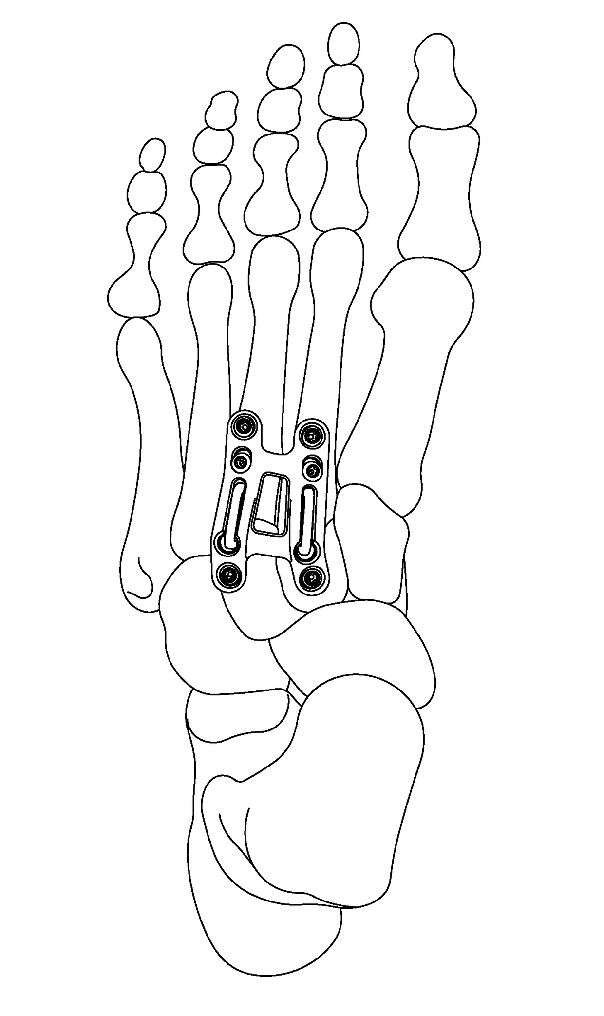
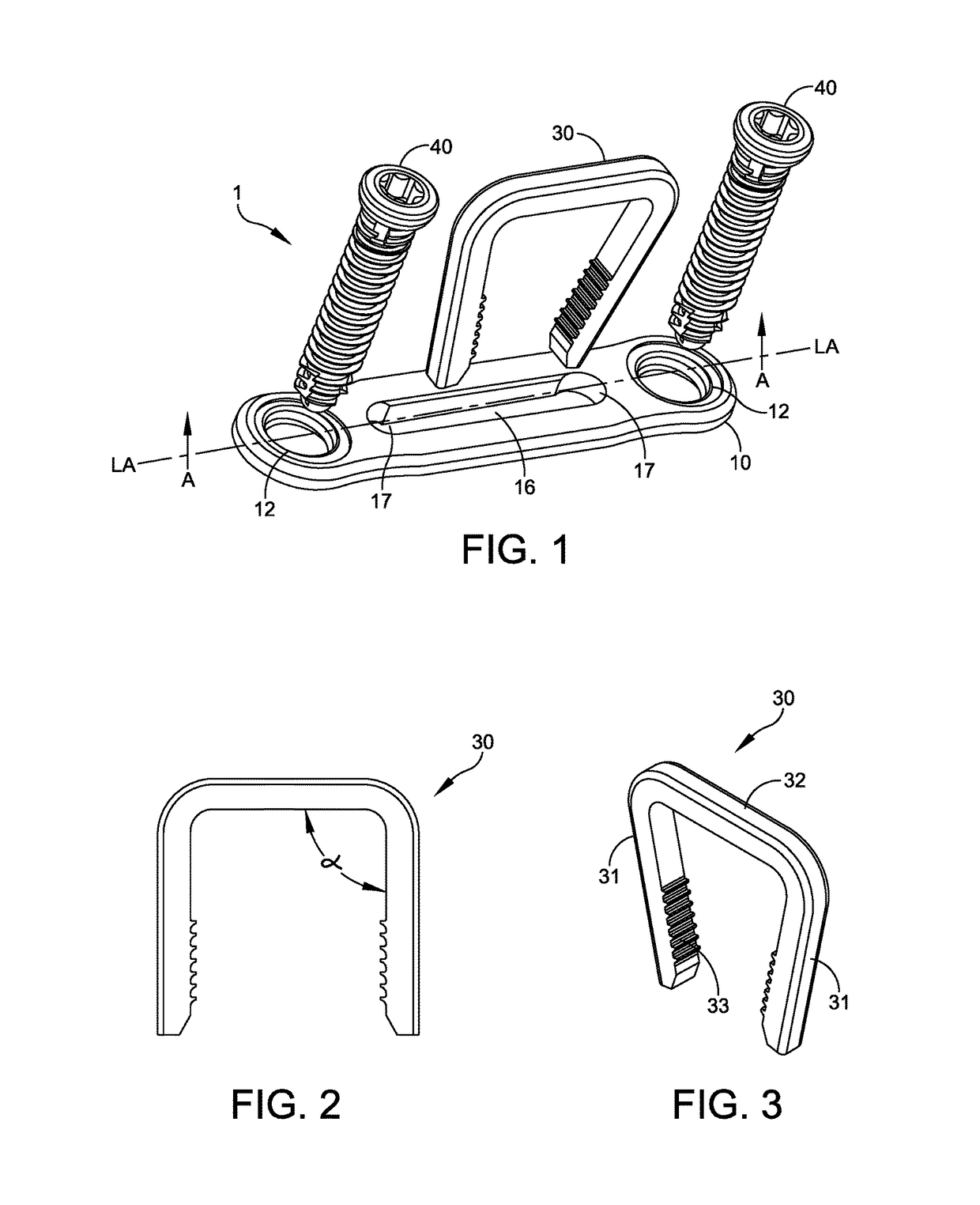
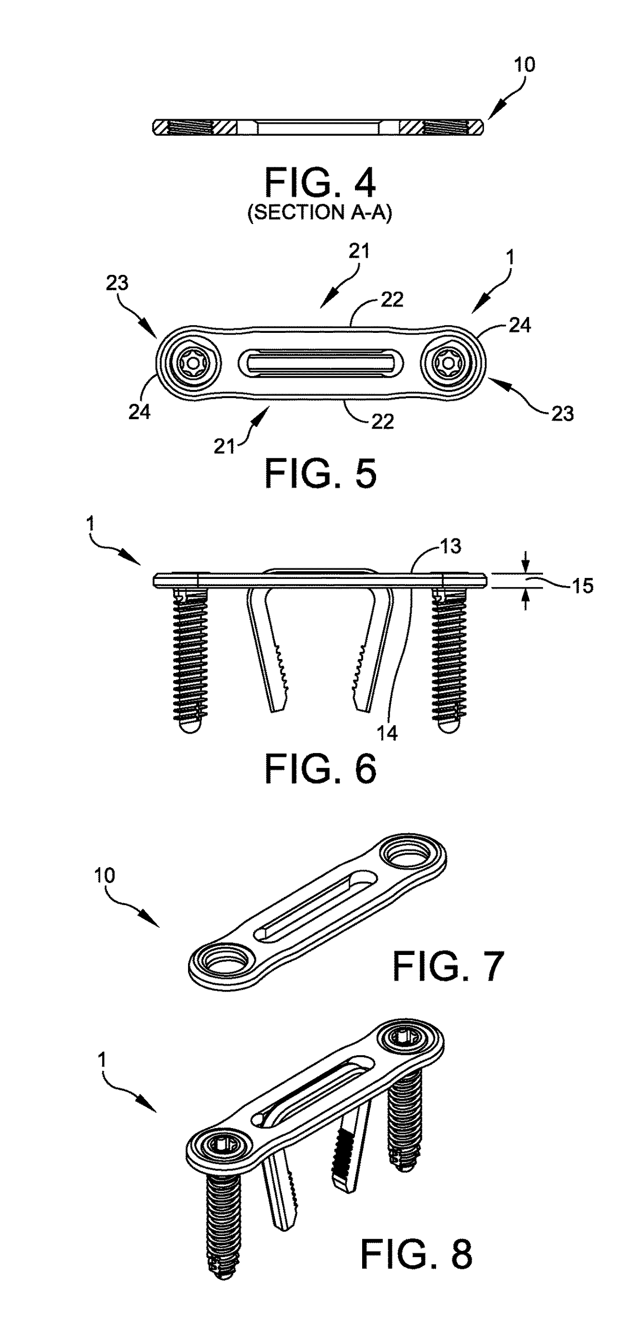
[0069]FIG. 1 illustrates active compression plate system 1 in an unassembled configuration, comprised of bone plate 10, bone staple 30, and one or more fasteners 40 in accordance with a first embodiment of the invention. In one example of use plate 10 is placed against a patient's bone, one fastener 40 is inserted through fastener hole 12 of plate 10 and affixed to the bone, one staple 30 is inserted through plate slot 16 and into the patents bone, and a second fastener 40 is inserted through fastener hole 12 in plate 10 and affixed to the bone. It should be noted that the term “slot”, refers to herein specifically as a full thickness recess or full thickness opening which extends from a first proximal plate surface to a second distal plate surface. With reference to FIGS. 1 to 8, active compression plate system 1 will be further described below.

[0070]Bone plate 10 may have a profile looking down from the top of a modified rectangle, with equivalent opposing parallel long sid...

embodiment 2

Slot

[0087]FIGS. 9 to 14 illustrate active compression plate system second embodiment 1′, comprised of bone plate 10′, bone staple 30′, and one or more fasteners 40′. In this second embodiment a plate slot can be coupled with either a staple or with screws, as further described below.

[0088]In active compression plate system second embodiment 1′, bone plate 10′, bone staple 30′, and fasteners 40′ have a similar structure and are made of the same materials as bone plate 10, bone staple 30, and fasteners 40 of active compression plate system 1, discussed above, except as noted below.

[0089]In active compression plate system second embodiment 1′, slotted portion 16′ of plate 10′ terminates at one end in a threaded through-hole 17a which can accommodate fastener 40′, in one embodiment a threaded locking screw and at the other end terminates in a second through-hole which is a ramped compression slot 17b, accommodating fastener 40′, in one embodiment a non-locking screw, to cause active com...

embodiment 5

Partial Thickness Recess

[0101]FIGS. 33 to 38 and 42 illustrate active compression plate system fifth embodiment 1″, comprised of bone plate 10″, bone staple 30″, and one or more fasteners 40″. In this fifth embodiment plate 10″ has a narrowed central width and is bent out of plane, as further described below.

[0102]In active compression plate system fifth embodiment 1″, bone plate 10″, bone staple 30″, and fasteners 40″ have the same structure and are made of the same materials as bone plate 10, bone staple 30, and fasteners 40 of active compression plate system 1, discussed above, except as noted below.

[0103]Bone plate 10″ is comprised of a taper inward or centrally from the ends of the plate as it progresses toward the transverse middle portion of the plate as is apparent from FIG. 35.

[0104]Bone plate 10″ is also comprised of an angled or bent portion in the intermediate portion nearer to one end than the other, and in one embodiment is designed for a dorsal fusion in the mid-foot....


PUM


Abstract

The invention comprises an orthopedic construct comprising an active compression orthopedic plate that can in the alternative, include either compression screws or an elastic or superelastic staple which is capable of inducing compression into the associated bone, and in alternative embodiments, the plate is a compound plate or has a translating portion which receives a leg of the bone staple.

Description

FIELD OF THE INVENTION[0001]The invention generally relates to an orthopedic construct comprising an orthopedic plate that provides for improved compression in associated bone, in particular, to achieve fusion. The plate can, in the alternative, include one or more compression screws, one or more staples, or both. The construct is capable of inducing compression into the associated bone, and in an alternative embodiment, the plate has a translating portion which is associated with at least either a screw (i.e., compression screw) or one leg of a bone staple.BACKGROUND OF THE INVENTION[0002]Orthopedic plating has been practiced for some time to repair osteotomy sites, bone fractures, and other sites where bones need to be held in close proximity to facilitate bone healing, in particular bone fusion. Typically a bone plate is affixed by means of screws to two or more bone portions so as to immobilize the portions relative to each other and thereby facilitate formation of a bone bridge...

Claims


Application Information

Patent Timeline
IPC IPC(8): A61B17/80A61B17/86A61B17/064
CPCA61B17/8014A61B17/8061A61B17/0642A61B2017/00004A61B2017/564A61B17/1655A61B2017/00867A61B17/86A61B17/8004A61B17/8023A61B17/8052A61B17/808A61B17/8057A61B17/809A61B2017/0645A61B17/8047
Inventor LEITHER, ANDREW J.PRASAD, PRIYA
Owner ORTHOHELIX SURGICAL DESIGNS
Why Eureka
Try Eureka