
Assist device, swinging joint device, linear motion variable rigidity unit, and machine tool

Inactive Publication Date: 2017-06-29
JTEKT CORP
View PDF0 Cites 23 Cited by
  • Summary
  • Abstract
  • Description
  • Claims
  • Application Information

AI Technical Summary

Benefits of technology

This patent describes a way to improve walking or running by giving a helping hand, while also reducing power consumption. It does this by automatically adjusting the rigidity of a joint that performs motion, which in turns adjusts the torque generated by the motion. This means that the electric motor that moves the body or the user's load is reduced. It also reduces the energy needed to move a linear body back and forth.

Problems solved by technology

Since the aforementioned single-leg walking assist device is configured such that the compression amount of the compression spring of the torque generator is adjusted with the use of the tool, it is impossible to adjust the spring force of the compression spring in accordance with a swinging angle of the femoral link portion during walking.
Therefore, it is difficult to assist the walking with high efficiency.
Further, it is also impossible to improve walking such that a walking motion of a user approaches an ideal walking motion.
This makes it difficult to reduce power consumption.
However, if supply of the electric power from a battery does not continue, the assistance cannot be provided.
Further, the user who needs walking assistance cannot carry a large and heavy battery, and therefore, it is presumed that a relatively small and lightweight battery is used.
This requires time and effort.

Method used


Image

  • Assist device, swinging joint device, linear motion variable rigidity unit, and machine tool
  • Assist device, swinging joint device, linear motion variable rigidity unit, and machine tool
  • Assist device, swinging joint device, linear motion variable rigidity unit, and machine tool

Examples


embodiment 1

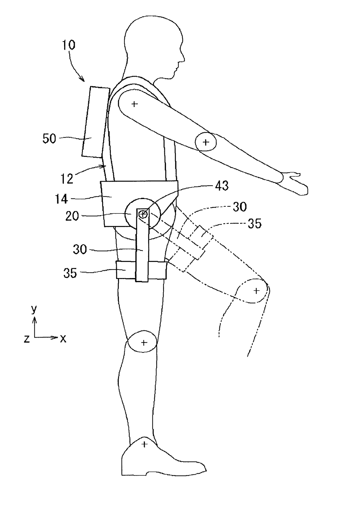
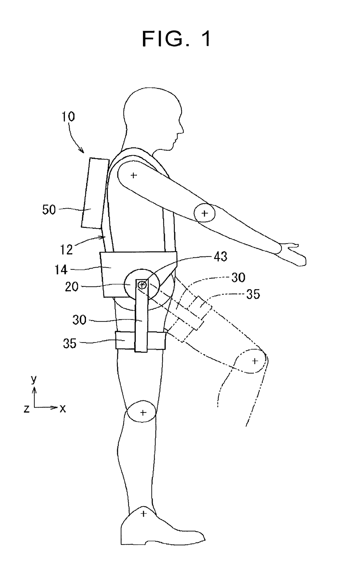
[0115]The following describes an assist device 10 of the disclosure based on FIGS. 1 to 10. The assist device 10 according to the present embodiment is a device that assists walk improvement of a user. Here, an x-direction, a y-direction, and a z-direction illustrated in the figures correspond to a forward direction, an upward direction, and a right-left direction with respect to a user who wears the assist device 10.

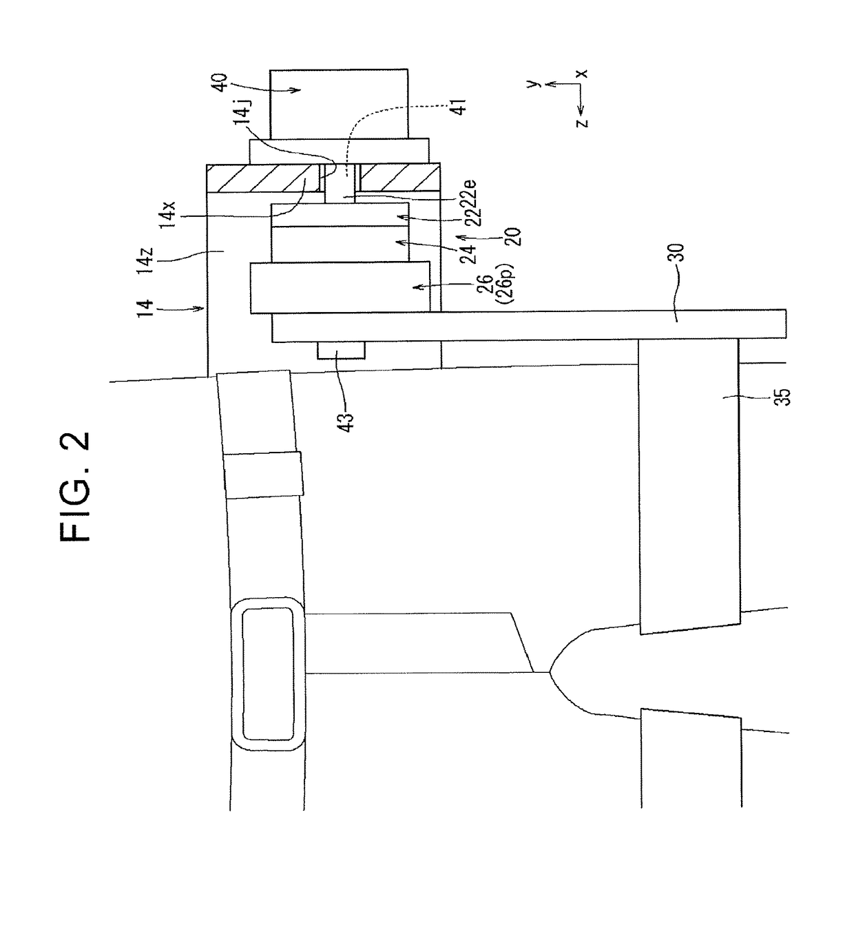
[0116]As illustrated in FIG. 1, the assist device 10 includes: an upper-body attachment member 12 put on an upper body and a lumbar part of a user; and a support frame portion 14 provided around a part of the upper-body attachment member 12 which corresponds to the lumbar part. As illustrated in FIG. 2, the support frame portion 14 includes: a back-face plate portion 14z provided so as to extend in the right-left direction on a back face of the upper-body attachment member 12; and side plate portions 14x provided on right and left sides of the back-face plate portion 1...

embodiment 3

[0157]The following describes an assist device 10 of the disclosure based on FIGS. 12 to 18. The assist device 10 of the present embodiment is a device configured to assist an upward rotation of an upper arm at the time when a user lifts a burden W. Here, an x-direction, a y-direction, and a z-direction illustrated in the figures correspond to a forward direction, an upward direction, and a leftward direction with respect to a user who wears the assist device 10.

[0158]As illustrated in FIG. 12, the assist device 10 includes: an upper-body attachment member 12 put on an upper body of a user; and a support frame portion 14 provided around an upper part of a back face of the upper-body attachment member 12. As illustrated in FIG. 13, the support frame portion 14 includes: a cross beam portion 14y provided on the upper part of the back face of the upper-body attachment member 12 so as to extend in the right-left direction; and side plate portions 14x provided on right and left sides of...

embodiment 5

[0288]A calculation method for the rotation angle θ1 of the electric motor 21 will be described. When a speed reducing ratio of a transmission is n, an efficiency of the transmission is η, and an original spring constant of the flat spiral spring is k1, and when it is assumed that forces are balanced, a driving torque τ of the output link (the femoral swinging arm) can be expressed as Expression 83 and Expression 84 as follows. Note that Expression 53 of Embodiment 5 shows θc=0.

τ=K(θ−θc)  Expression 83

τ=ηnτ1  Expression 84

[0289]Here, τ1 is a torque that occurs on an input side (an electric motor 21-side) of the transmission and can be expressed as Expression 85 with a rotation angle θ of the output link (the femoral swinging arm) and the rotation angle θ1 of the rigidity adjustment member 23 (the rotation angle of the electric motor 21) as follows.

τ1=k1(nθ−θ1)  Expression 85

[0290]When Expression 85 is substituted into Expression 84, Expression 86 can be obtained.

τ=ηnk1(nθ−θ1)  Expre...


PUM


Abstract

An assist device is connected to a moving body that performs a reciprocating swing motion. The assist device includes a first output portion configured to swing around a swing center as a center of a swing motion; a variable rigidity device including an elastic body configured to accumulate energy and release the energy in accordance with a first swinging angle as a swinging angle of the first output portion, and a rigidity varying unit configured to change an apparent rigidity of the elastic body seen from the first output portion; a first angle detecting portion configured to detect the first swinging angle; and a control device configured to adjust the apparent rigidity of the elastic body seen from the first output portion by controlling the rigidity varying unit in accordance with the first swinging angle detected by the first angle detecting portion.

Description

INCORPORATION BY REFERENCE[0001]The disclosure of Japanese Patent Applications No. 2015-252041, 2015-252042, 2015-252043 and 2015-252044 filed on Dec. 24, 2015 each including the specification, drawings and abstract is incorporated herein by reference in its entirety.BACKGROUND[0002]1. Technical Field[0003]The disclosure relates to an assist device that assists walking improvement, an operation, and the like of a user. Further, the disclosure relates to a swinging joint device which performs a periodic swing motion and which is able to change a rigidity of a joint. Further, the disclosure relates to a linear motion variable rigidity unit and a machine tool including a linear motion variable rigidity unit.[0004]2. Description of Related Art[0005]An assist device that assists walking or the like of a user is described in Japanese Patent Application Publication No. 2013-236741 (JP 2013-236741 A), Japanese Patent Application Publication No. 2013-173190 (JP 2013-173190 A), and the like, ...

Claims


Application Information

Patent Timeline
IPC IPC(8): A61H3/00
CPCA61H3/008A61H2201/123A61H2201/149A61H2201/50A61H2201/1642A61H2201/5084A61H2201/163B23Q1/26B23Q1/64B23Q5/34B25J9/0006A61H2201/1614A61H1/0244A61H1/0281A61H3/00B25J13/088B25J17/0208A61H2201/1463A61H2201/1623A61H2201/1628A61H2201/1635A61H2201/165A61H2201/1652A61H2201/1676A61H2201/5064A61H2201/5069
Inventor OHTA, HIROMICHIYOSHIMI, YOSHITAKAOHTSUBO, KAZUYOSHI
Owner JTEKT CORP
Learn More