Rotary engine

a rotary engine and rotor technology, applied in the direction of combustion engines, pump components, sealing arrangements of engines, etc., can solve the problems of reducing fuel efficiency and operation efficiency, reducing so as to improve the efficiency of rotary engines.

Active Publication Date: 2017-06-29
LG ELECTRONICS INC
View PDF3 Cites 5 Cited by
  • Summary
  • Abstract
  • Description
  • Claims
  • Application Information

AI Technical Summary

Benefits of technology

[0049]Specifically, the check valve-type control unit can have an advantage, compared with the basic control unit, in that unburned gas partially generated at a side of the combustion chamber is prevented from flowing to the opposite side of the combustion chamber by virtue of the cover. As such, the check valve-type control unit can much more reduce an amount of unburned gas generated that the basic control unit, and can execute combustion similar to actual constant volume combustion.
[0050]In the rotary engine disclosed herein, intake port and exhaust port provided on the rotor may be located at positions where introduced gas can be exhausted after being expanded to a greater amount, thereby acquiring an overexpansion effect that an expansion ratio is greater than a compression ratio. Efficiency of the rotary engine can thus be improved by combination of such overexpansion effect with an effect of limiting a volume of an operation chamber by the combustion controller during a combustion period.

Problems solved by technology

However, as the rotary engine has a wider surface area than a stroke volume, an extinction area increases.
Accordingly, the rotary engine emits a large quantity of unburned hydrocarbon (UHC) and causes lowered fuel efficiency and operation efficiency.
Hence, designs for inner shapes of the rotor and a housing related to the rotor may be slightly complicated.
However, for the rotary engine, force is applied to push the piston during the compression, and accordingly additional operations are needed.
This causes a limit in increasing efficiency of the engine.
Therefore, such structure of the rotary engine is hardly understood as a structure capable of fundamentally solving an excessive emission of unburned gas.

Method used


Image

  • Rotary engine
  • Rotary engine
  • Rotary engine

Examples


Embodiment Construction

[0081]Description will now be given in detail of a rotary engine according to exemplary embodiments disclosed herein, with reference to the accompanying drawings.

[0082]A singular representation may include a plural representation unless it represents a definitely different meaning from the context.

[0083]In describing the present invention, if a detailed explanation for a related known function or construction is considered to unnecessarily divert the gist of the present disclosure, such explanation has been omitted but would be understood by those skilled in the art.

[0084]The present invention has been explained with reference to the embodiments which are merely exemplary. It will be apparent to those skilled in the art that various modifications and variations can be made in the present invention without departing from the spirit or scope of the invention.

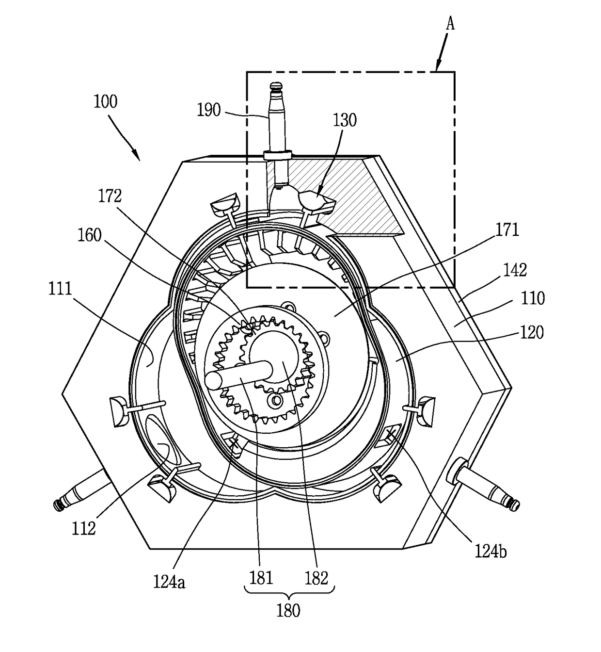
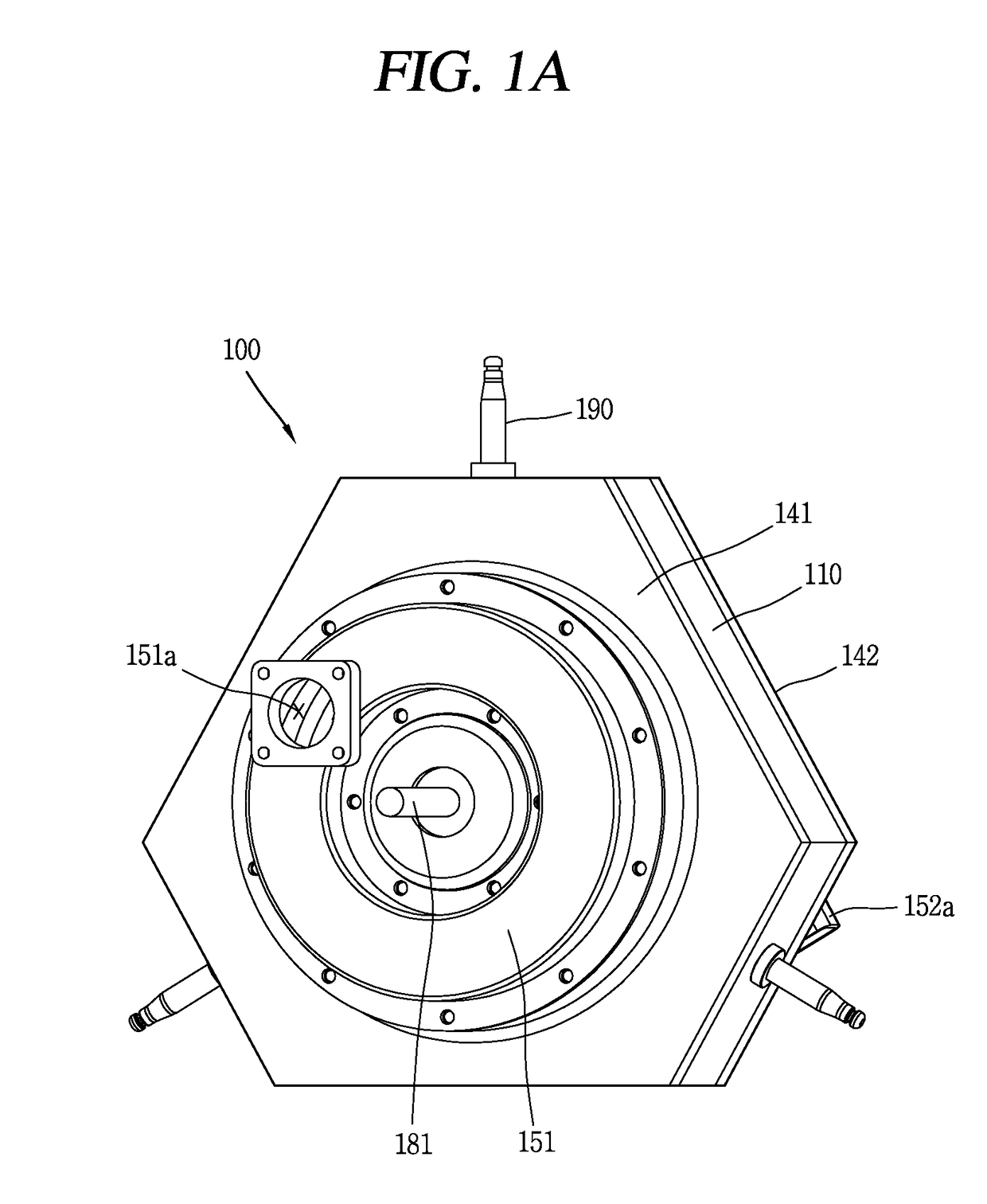
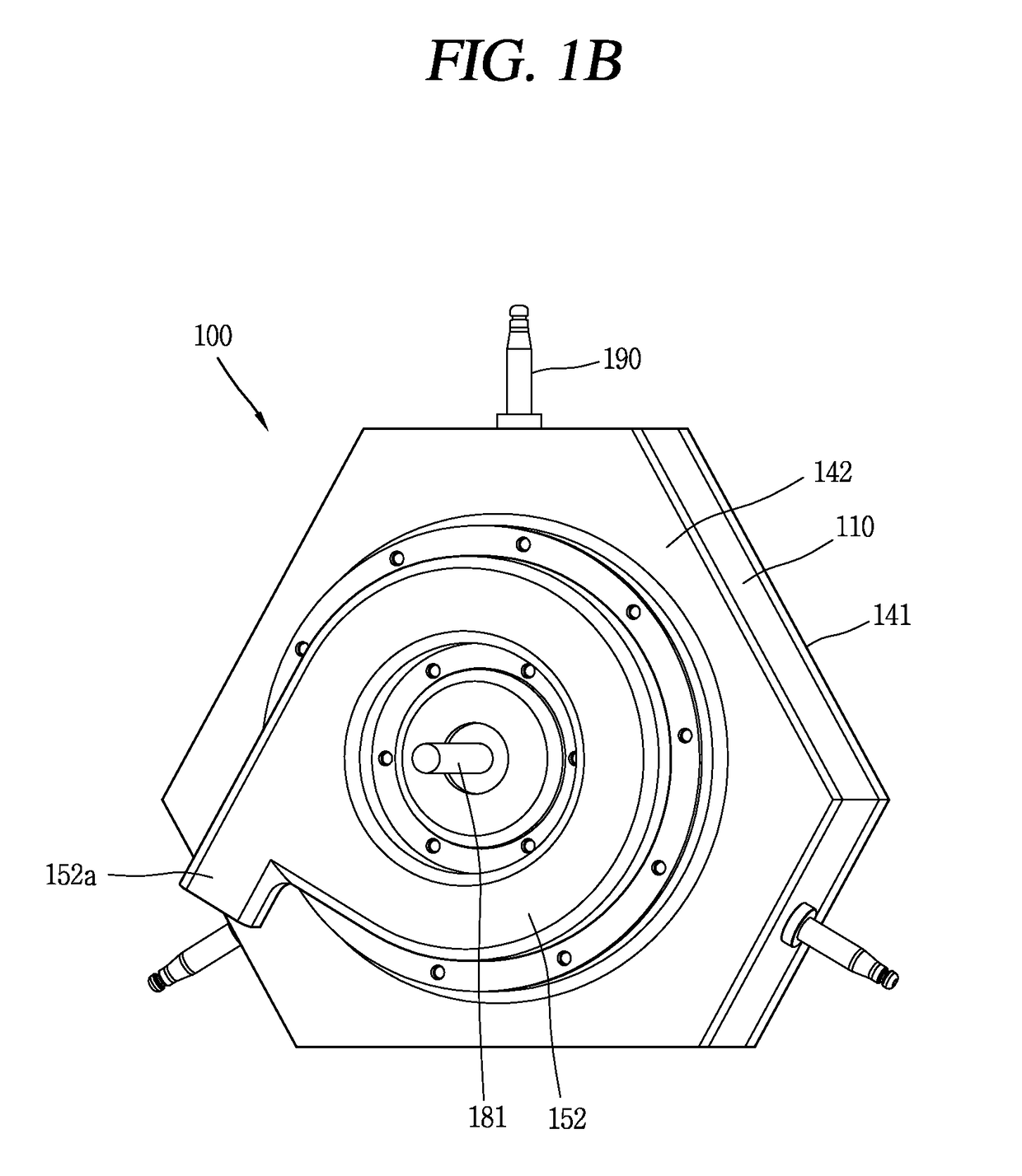
[0085]FIGS. 1A and 1B are perspective views illustrating a rotary engine 100 in accordance with one embodiment of the present in...


PUM


Abstract

The present invention provides a rotary engine including a housing having therein N rob accommodating portions (N is a natural number equal to or greater than 3), and combustion chambers communicating with the rob accommodating portions, respectively, a rotor having N−1 robs eccentrically rotating centering on a center of the rob accommodating portions, and consecutively accommodated in the respective rob accommodating portions during the eccentric rotation, and combustion controllers provided at both sides of each combustion chamber, and configured to limit a combustion range of mixed gas, whereby an excessive emission of unburned gas caused in an existing rotary engine can be overcome, efficiency of the engine can be improved, and a rotary engine with an optimized design condition can be provided.

Description

CROSS-REFERENCE TO RELATED APPLICATION(S)[0001]Pursuant to 35 U.S.C. §119(a), this application claims the benefit of an earlier filing date of and the right of priority to Korean Application No. 10-2015-0185404, filed on Dec. 23, 2015, the contents of which are incorporated by reference herein in its entirety.BACKGROUND[0002]1. Field[0003]This specification relates to a rotary engine producing driving force by a rotary motion.[0004]2. Background[0005]A rotary engine is an engine producing driving force by a rotary motion, and has first been invented by Wankel.[0006]A Wankel engine invented by Wankel includes a housing having an inner surface in a shape of an epitrochoidal curve, and a rotor having a triangular shape rotating within the housing. An inner space of the housing is divided into three spaces by the rotor. As volumes of those spaces change in response to the rotation of the rotor, four strokes such as intake→compression→explosion→exhaust are executed in a continuous manner...

Claims


Application Information

Patent Timeline
Patent Type & Authority Applications(United States)
IPC IPC(8): F02B55/08F02B53/04
CPCF02B53/04F02B55/08F01C1/22F01C19/025F04C2250/00Y02T10/12F02B2053/005
Inventor YU, BYEONGHUNLEE, YUNHILEE, CHANGEONLEE, BYEONGCHULLEE, KAMGYU
Owner LG ELECTRONICS INC
Why Eureka
Try Eureka