Integratable Movement Device for Ventilating Equipment

a technology of ventilating equipment and movement device, which is applied in the direction of ventilation system, lighting and heating apparatus, heating type, etc., can solve the problems of uneven air blowing, product quality issues, inefficiency in assembly, etc., and achieve the effect of improving the production efficiency of ventilating equipment, ensuring product quality, and simplifying assembly

Inactive Publication Date: 2017-06-29
SHENZHEN SUNZONE ELECTRICAL APPLIANCES
View PDF7 Cites 2 Cited by
  • Summary
  • Abstract
  • Description
  • Claims
  • Application Information

AI Technical Summary

Benefits of technology

[0007]The objective of the present invention is to solve the above conventional drawbacks and to provide an integratable movement device for ventilating equipment that integrates heating and cooling components and blowing and exhaling components and is able to assemble flexibly to form various products, allowing multi-directional air blowing, simplification of the assembling, the increase of production efficiency of such ventilating equipments significantly, and a guarantee of the product quality of the integratable movement device for ventilation equipment of the present invention.

Problems solved by technology

The components of the conventional heater and cooling fan are made independently and then assembled in the case respectively that not only complicates the manufacturing process, but also results inefficiency in assemble and causes product quality issues.
Besides, there is only one vent outlet provided at a front side of the conventional heaters and cooling fans for blowing out air directly here through the rotation of the fans of the air blower thereof that results in uneven air blowing and generating more noise.

Method used


Image

  • Integratable Movement Device for Ventilating Equipment
  • Integratable Movement Device for Ventilating Equipment
  • Integratable Movement Device for Ventilating Equipment

Examples


first embodiment

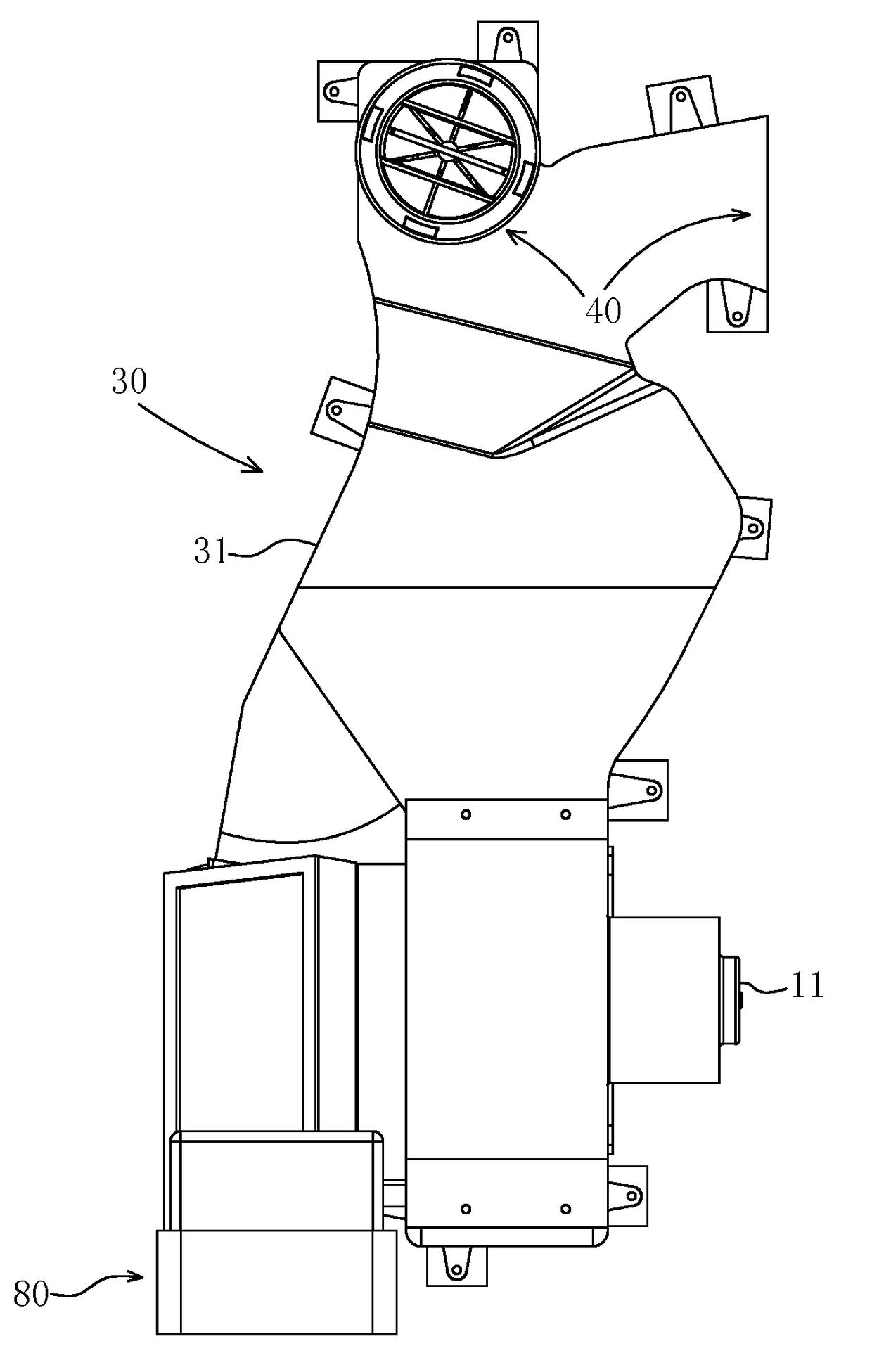
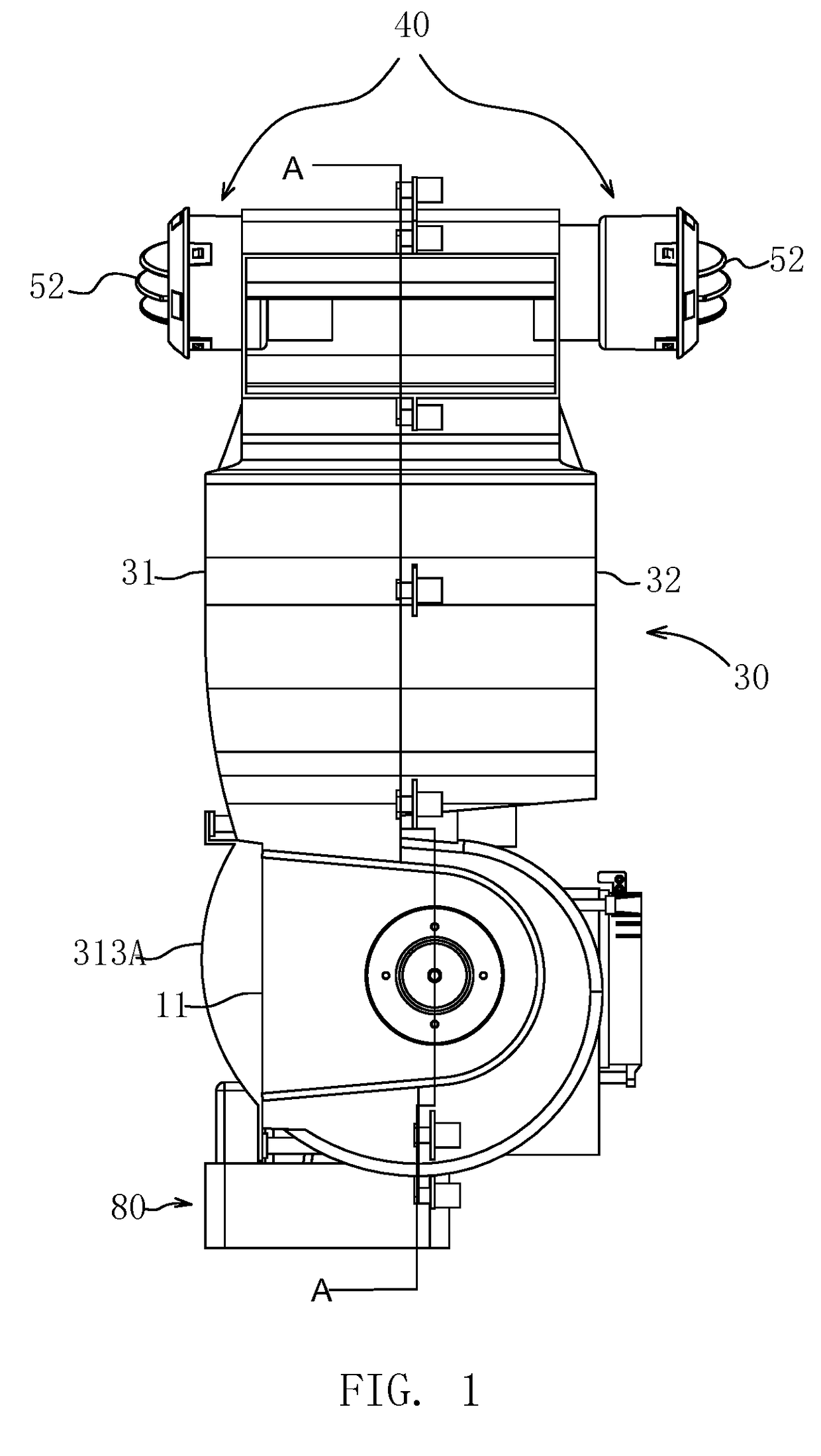
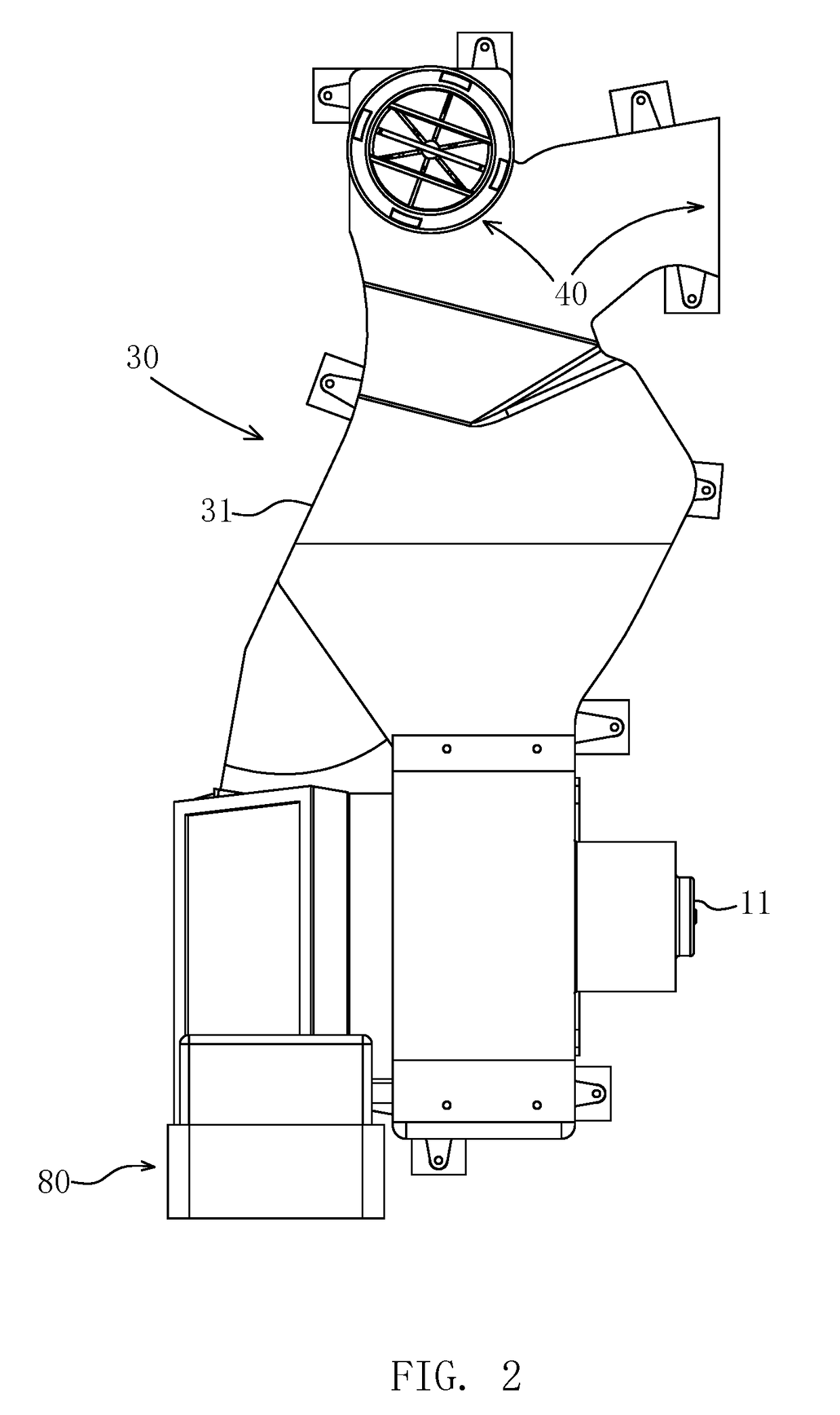
[0036]Referring to what FIGS. 4 to 7, a first embodiment of the present invention is illustrated, wherein the integratable movement device comprises a housing 30. The housing 30 includes shaped pair of left shell 31 and right shell 32 symmetrically constructed in shape, wherein the left shell 31 and the right shell 32 are coupled into the housing 30 with screws.

[0037]The housing 30 has at least a venting outlet 40 integrally formed in an upper portion thereof. The housing 30 may have only one or venting outlet 40 or more than one venting outlets 40 provided therein. When there is only one vent outlet 40 provided, it is provided at the upper front portion of the housing 30, wherein the venting outlet unit 50 comprises a front venting outlet unit 51 provided at the front venting outlet 40. When there are more than one venting outlets 40 provided, they can be provided in the front, left, and right sides of the housing 30 respectively, wherein the venting outlet unit 50 comprises the fr...

second embodiment

[0047]FIGS. 9 and 11 illustrate a heater device assembled from an integratable movement device according to one embodiment of the present invention. Referring to FIG. 9, a lower portion of the housing 30 contained a PCT heating component 70 which installed between the fan wheel 20 and the first grid shaped venting inlet 313 provided in the lower portion of the housing 30. The PCT heating component 70, the housing 30, the venting outlets 40 provided in the housing 30, the venting channel 60, the venting outlet units 50 secured at each of the venting outlets 40, and the electric machine 10 and fan wheel 20 secured in the housing constructed the integratable movement device being directly assembled into a heater device.

[0048]Referring to FIG. 9, the PCT heating element 70 includes a PCT heating body 71 and a PCT heating body frame 72. The PCT heating body 71 comprises a plurality of PCT heating element units 711 connected together. The PCT heating body frame 72 is a rectangular frame a...

third embodiment

[0050]In one embodiment of the present invention as shown in FIGS. 10 and 11, the integratable movement device of the present invention integrates a cooling component 80 to form an integratable cooling fan movement device that can be directly assembled into a cooling fan device.

[0051]Referring to FIG. 9, a lower portion of the housing 30, opposite to the fan wheel 20, contains a cooling component 80 that is able to be assembled to form a cooling fan movement device. The cooling component 80 is installed between the fan wheel 20 and the venting inlet 313 in the lower portion of the housing 30. The cooling element 80, the movement housing 30, the venting outlets 40 provided in the housing 30, the venting channel 60, the venting outlet units 50 secured at each of the venting outlets 40 respectively, and the electric machine 10 and the fan wheel 20 secured in the housing 30 constructs an integratable cooling fan movement device that is able to be directly assembled into a cooling fan de...


PUM


Abstract

An integratable movement device for ventilating equipment includes an electric machine such as a motor and a fan wheel connected with the electric machine. The movement device further includes a housing, wherein the electric machine and the fan wheel are installed in an inner lower portion of the housing. An upper portion of the housing integrally forms one or more venting outlets. A plurality of venting outlet units is provided at the venting outlets respectively. A chamber provided between the venting outlets and the fan wheel in the housing defines a venting channel. The housing having the venting outlets and the venting channel, along with the venting outlet units, the electric machine and the fan wheel configure the integratable movement device that is able to be directly assembled into the ventilating equipment.

Description

NOTICE OF COPYRIGHT[0001]A portion of the disclosure of this patent document contains material which is subject to copyright protection. The copyright owner has no objection to any reproduction by anyone of the patent disclosure, as it appears in the United States Patent and Trademark Office patent files or records, but otherwise reserves all copyright rights whatsoever.BACKGROUND OF THE PRESENT INVENTION[0002]Field of Invention[0003]This invention relates to ventilating equipment such as air cooler and heater, in particular, to a movement mechanism adapted to be used as an air blower device, which is an integratable movement device for ventilating equipment, providing multi-directional air blowing ability and being able to be assembled and arranged flexibly.[0004]Description of Related Arts[0005]Various air conditioning equipments, such as air conditioners, electric fans, heaters, cooling fans, are commonly used in our daily lives. Among these devices, air conditioners use medium l...

Claims


Application Information

Patent Timeline
Patent Type & Authority Applications(United States)
IPC IPC(8): F24F1/00F24H3/02
CPCF24H3/022F24F1/0011F24F5/0035F24F7/007Y02B30/54
Inventor GAO, TIANYU
Owner SHENZHEN SUNZONE ELECTRICAL APPLIANCES
Why Eureka
Try Eureka