3D Printing

a technology of additive manufacturing and 3d printing, which is applied in the direction of additive manufacturing process, manufacturing driving means, additive manufacturing with solids, etc., can solve the problems of large diameter and thin cross-section of annular parts such as duo-cone seals (face seals) that are difficult to manufacture using conventional methods, and the use of such techniques is difficult to achieve on a production scal

Active Publication Date: 2017-07-06
CATERPILLAR INC
View PDF3 Cites 40 Cited by
  • Summary
  • Abstract
  • Description
  • Claims
  • Application Information

AI Technical Summary

Problems solved by technology

Parts, and in particular relatively large diameter contoured or annular parts, with relatively thin cross-sections may be difficult to manufacture using conventional methods.
For example, an annular part such as a duo-cone seal (face seal) that has a large diameter and a thin cross-section may be difficult to manufacture using conventional methods.
While such a part may benefit from additive manufacturing that uses 3D printing techniques such as selective laser sintering or selective laser melting, the large diameters of such parts make the use of such techniques difficult to implement on a production scale while maintaining consistency and quality for the part.

Method used


Image

  • 3D Printing
  • 3D Printing
  • 3D Printing

Examples


Embodiment Construction

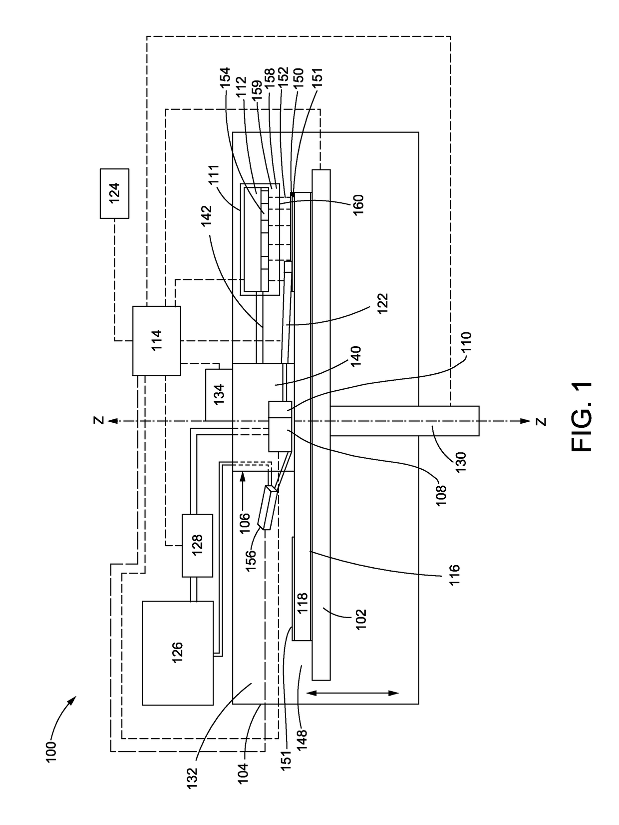
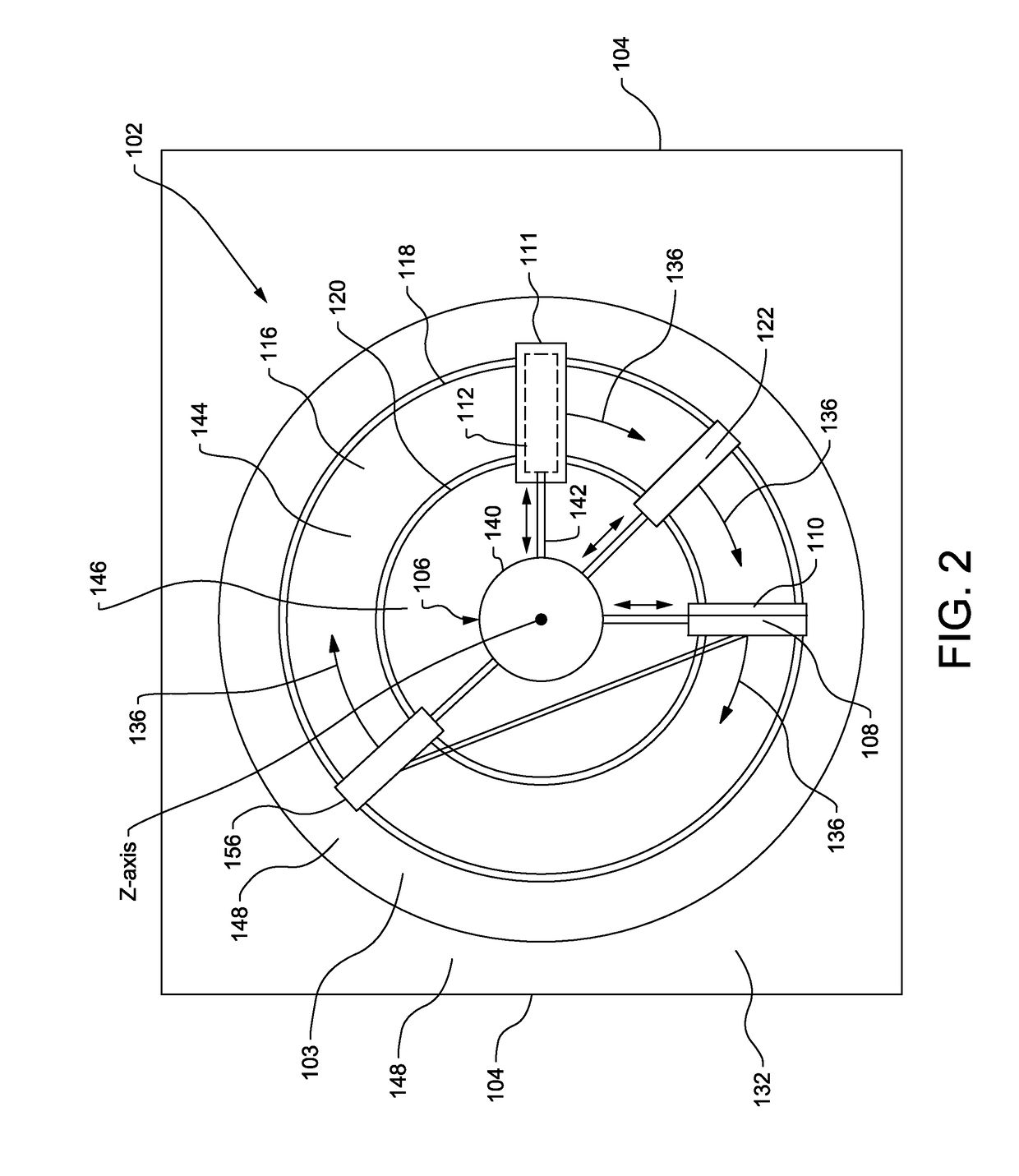
[0014]FIG. 1 is an embodiment of a schematic diagram of a system 100 according to this disclosure. While this disclosure is provided with reference to the manufacturing of a duo cone seal, and in particular a duo cone seal with a large diameter, it will be understood that the teachings of this disclosure may be employed with equal efficacy in conjunction with other parts or assemblies such as rings, gears or the like. The teachings of this disclosure may also be used with other parts that are not annular in shape.

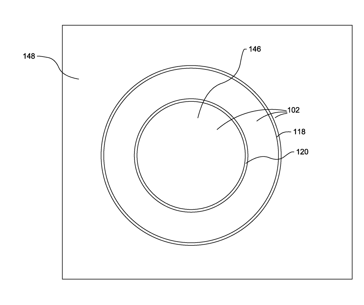
[0015]The system 100 may include a platform 102, a housing 104, a gantry 106, a dispenser 108, a first press 110, a laser 112, a positive pressure chamber 111 and a controller 114. The system 100 may include a plate 116. The system 100 may also include an outer retaining wall 118 and an inner retaining wall 120. In some embodiments, the system 100 may include a second press 122. The system 100 may also include a user interface 124, a powder repository 126 and a powder feed ...


PUM

PropertyMeasurementUnit
degree of freedomaaaaaaaaaa
reflectionaaaaaaaaaa
polar coordinatesaaaaaaaaaa

Abstract

A system and method for Selective Laser Fusing of a 3D part is disclosed. The system may comprise a platform, a gantry, a dispenser, a first press, a laser configured to emit a laser beam onto powdered material, a positive pressure chamber at least partially surrounding the laser, and a controller. The controller may be configured to: (a) receive data that includes a representation of the 3D part sliced into a plurality of layers; (b) rotate on a path about an axis either the platform or simultaneously each of the dispenser, the first press, the positive pressure chamber and the laser; (c) activate the dispenser to deposit the powdered material during (b); (d) activate the laser to emit during (b) the laser beam onto the powdered material to Fuse the powdered material into a layer of the plurality of layers; and (e) repeat (b)-(d) to make the 3D part.

Description

TECHNICAL FIELD[0001]The present disclosure relates to additive manufacturing and, more particularly, to additive manufacturing of large annular or contoured parts.BACKGROUND[0002]Additive manufacturing methods may include 3D printing techniques such as selective laser sintering or selective laser melting in which a 3D part is produced layer by layer by irradiating with a laser beam a powder bed of material contained within a chamber. Selective laser sintering uses a laser to sinter material together. Selective laser melting is similar but uses a laser to fully melt (rather than sinter) the material together, thus allowing for different properties such as crystal structure, porosity and the like. As used herein selective laser sintering and selective laser melting may be referred to, collectively, as “Selective Laser Fusing.” Similarly, as used herein, sintering and melting may be collectively referred to as “Fusing” or “Fuse” or “Fused.”[0003]For Selective Laser Fusing, the digital...

Claims


Application Information

Patent Timeline
Patent Type & Authority Applications(United States)
IPC IPC(8): B29C67/00
CPCB29C67/0077B33Y10/00B33Y50/00B33Y30/00B29C64/153B29C64/241
Inventor THORSON, TIMOTHYMARCHIONE, THIERRY A.
Owner CATERPILLAR INC
Why Eureka
Try Eureka