
Conveyor with integrated dust collector system

a technology of dust collector and conveyer, which is applied in the direction of chutes, transportation and packaging, and well accessories, etc., can solve the problems of reducing the risk of dust exposur

Active Publication Date: 2017-07-06
SANDBOX ENTERPRISES LLC
View PDF0 Cites 32 Cited by
  • Summary
  • Abstract
  • Description
  • Claims
  • Application Information

AI Technical Summary

Benefits of technology

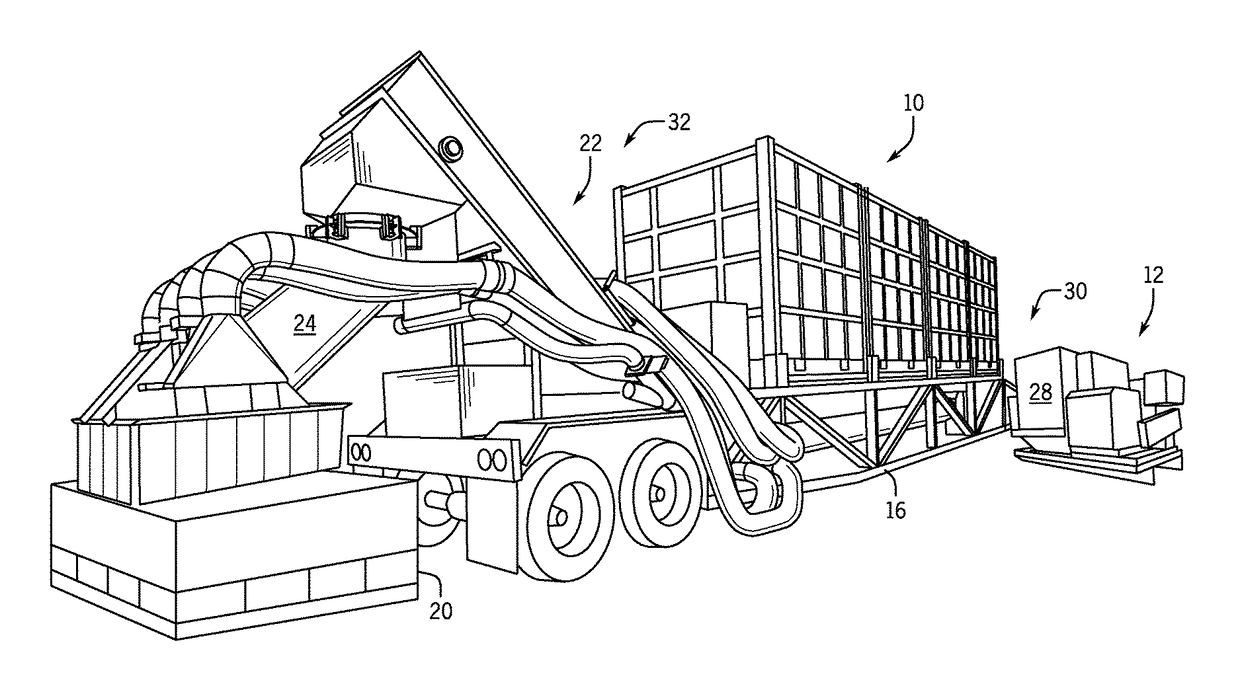
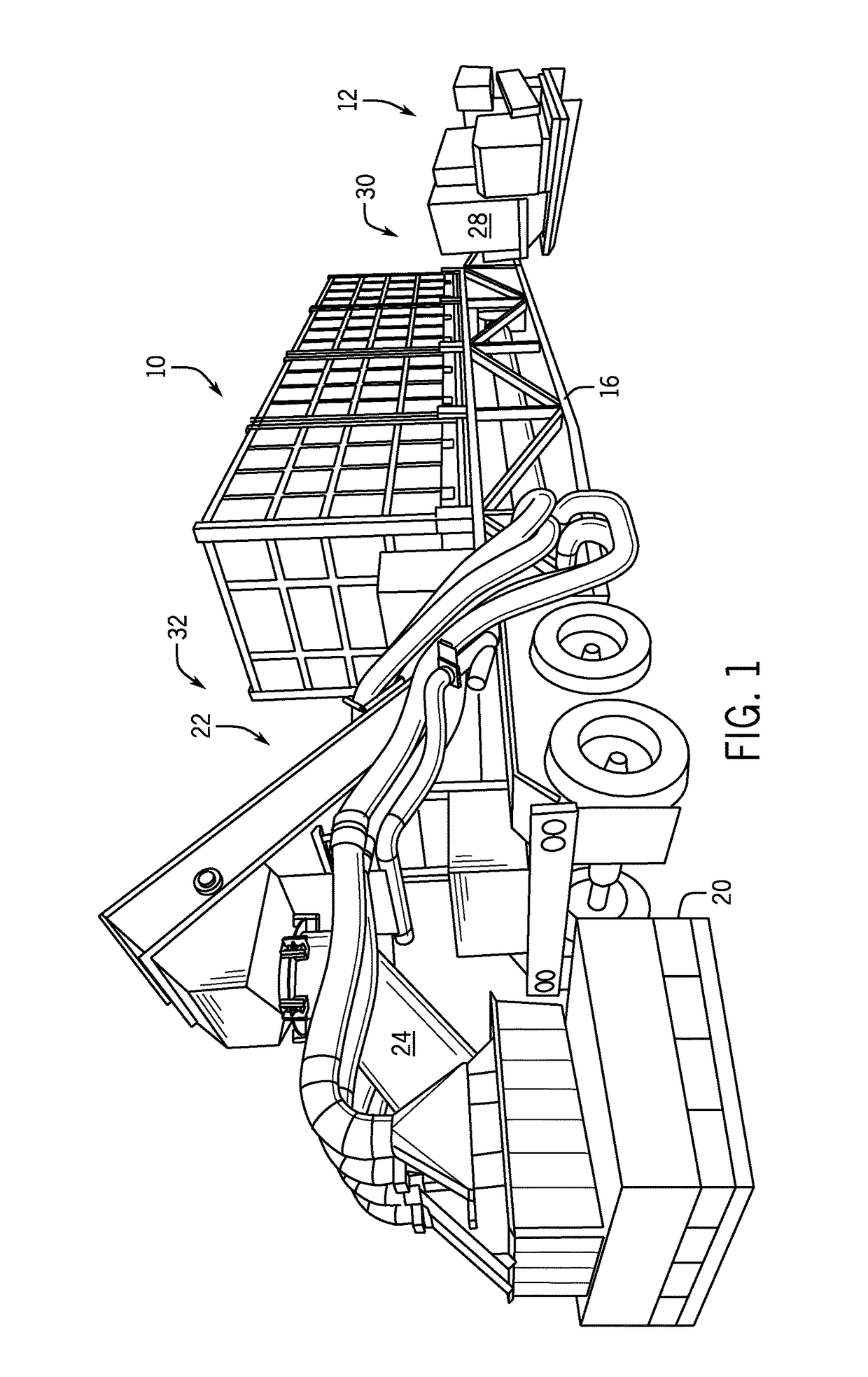
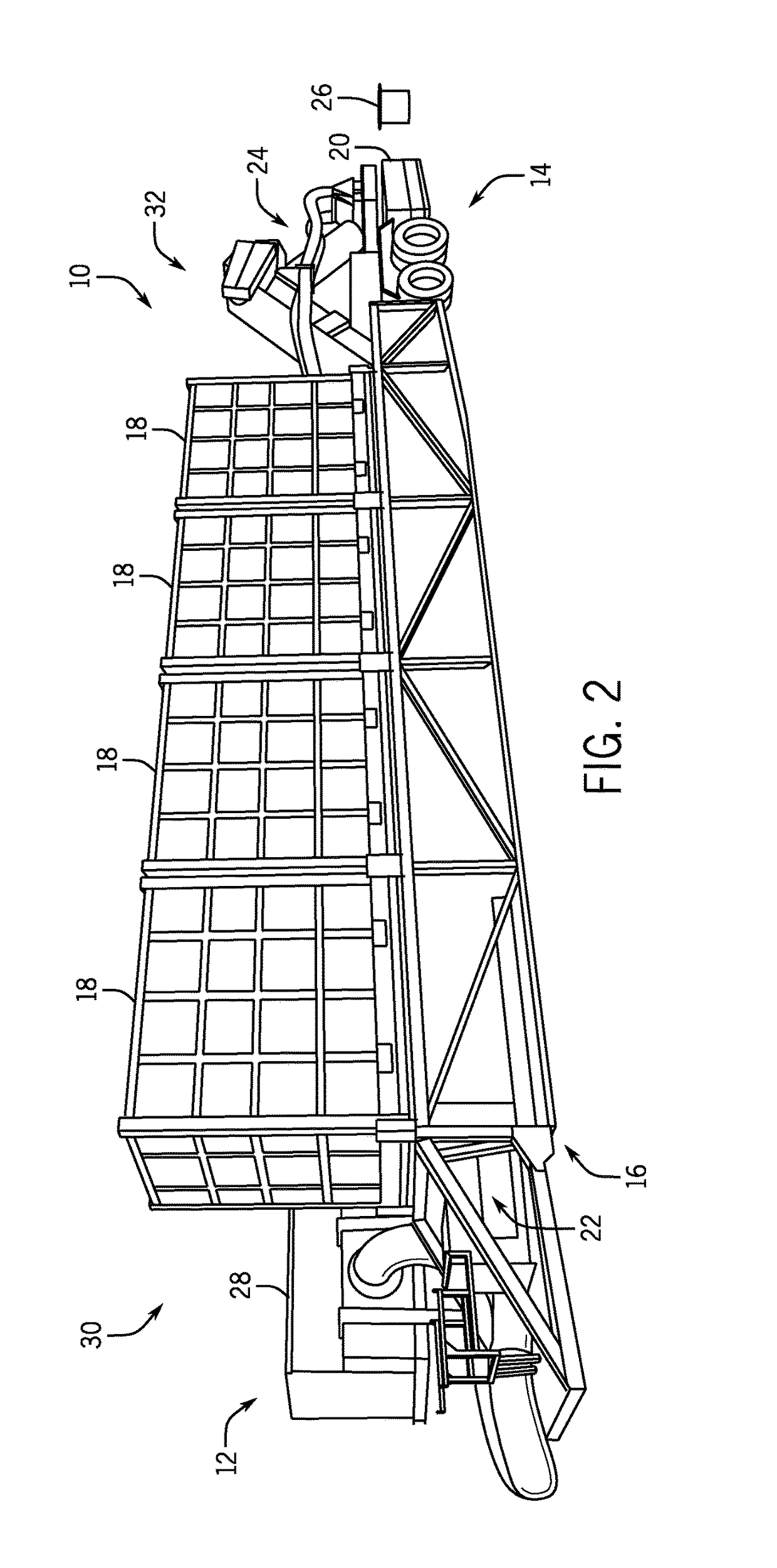
The patent text describes a system for capturing proppant dust particles when positioned at a fracking operation site. The system includes a proppant delivery assembly to dispense proppant from containers and a dust collection assembly positioned to capture dust particles released during the dispensing process. The dust collection assembly directs an air flow to capture the dust particles and move them away from the proppant, reducing the risk of dust exposure to personnel. The technical effect of the system is to provide a safer workplace by minimizing the risk of health hazards associated with dust exposure during fracking operations.

Problems solved by technology

This type of proppant, however, may break down or crush more readily under stress due to the relatively fewer grain-to-grain contact points to bear the stress often incurred in deep oil- and gas-bearing formations.
The movement and loading of the fracking proppant may produce dust particles which may be inhaled by operations personnel or sucked into mechanical equipment.
Inhalation by personnel may negatively impact health.
Moreover, mechanical equipment may be damaged by the dust particles.
For example, the particles may clog filters and reduce air flow to the equipment.

Method used


Image

  • Conveyor with integrated dust collector system
  • Conveyor with integrated dust collector system
  • Conveyor with integrated dust collector system

Examples


first embodiment

[0143]FIG. 31 is a back elevation view of the air mover 28 with a waste discharge assembly 430 coupled to the discharge 424, according to the present invention. As described, the engine 52 is coupled to the air mover 28 to provide operational power. A guard 432 blocks access to the coupling between the air mover 28 and the engine 52. The discharge 424 extends off of the side of the air mover 28 for removal of the dust particles 264 and residual proppant 354 collected by the dust collection assembly 12. In the illustrated embodiment, a flexible hose 434 is coupled to the discharge to direct the dust particles 264 and the residual proppant 354 into a drum 436. The drum 436 has a removable lid 438 that blocks access to the interior of the drum 436 when the dust particles 264 and the residual proppant 354 is being transferred to the drum 436. As a result, the dust particles 264 are substantially confined to the drum 436 to reduce the likelihood of exposure to operations personnel. In ce...

second embodiment

[0144]FIG. 32 is a back elevation view of the air mover 28 and the waste discharge 430, assembly according to the present invention. As described above, the dust particles 264 and residual proppant 354 captured by the air mover 28 via the hood assembly 42 and the catch box 104 is carried back to the air mover 28 via the air flow 266. The captured particles are filtered out by the filter elements and removed from the system via the discharge 424. In the illustrated embodiment, the drum 436 is positioned on a set of wheels 440 to facilitate movement of the drum 436. The particles flow out of the discharge 424 and into the drum 436 via the flexible hose 434. Thereafter, the drum 436 can be removed from the air mover 28, for example, when the drum 436 is full. The wheels 440 enable easier movement of the drum 436, thereby reducing the time period between changing full drums 436 for empty drums 436.

[0145]FIG. 33 is a perspective view of the proppant delivery assembly 10 and the dust coll...


PUM


Abstract

Embodiments of the present disclosure a system for capturing proppant dust particles when positioned at a fracking operation site including a proppant delivery assembly to receive one or more containers having proppant stored therein. The system dispenses the proppant from the one or more containers and delivers the proppant to other fracking operation equipment. Moreover, the system includes a dust collection assembly positioned proximate and associated with the proppant delivery assembly to capture dust particles released by movement and settling of the proppant when being dispensed and delivered by the proppant delivery assembly. The dust collection assembly is positioned to direct an air flow in a flow path overlying the dust particles to capture the dust particles and move the dust particles away from the proppant thereby reducing risk of dust exposure to fracking operation site personnel.

Description

RELATED APPLICATIONS[0001]This application claims priority to U.S. Provisional Application No. 62 / 275,377, filed Jan. 6, 2016, titled “Conveyor with Integrated Dust Collector System,” which is incorporated by reference in its entirety.BACKGROUND[0002]1. Field of the Invention[0003]The present invention relates to collecting dust particles. More particularly, the present invention relates to systems and methods to collect dust particles formed during the movement of proppant.[0004]2. Description of Related Art[0005]Hydraulic fracturing or “fracking” has been used for decades to stimulate production from conventional oil and gas wells. In recent years, the use of fracking has increased due to the development of new drilling technology such as horizontal drilling and multi-stage fracking. Such techniques reach previously-unavailable deposits of natural gas and oil. Fracking generally includes pumping fluid into a wellbore at high pressure. Inside the wellbore, the fluid is forced into ...

Claims


Application Information

Patent Timeline
Patent Type & Authority Applications(United States)
IPC IPC(8): B65G69/18B65G65/42B65G53/26B65G11/00B65G15/00
CPCB65G69/181B65G11/00B65G15/00E21B41/00B65G65/42E21B43/267B65G53/26B65G69/182E21B43/2607B01F33/5021B65G53/24B65C11/00
Inventor OREN, JOSHUABOROS, MARTYBERVEILER, PETEHANSEN, DAVECAMPBELL, COLINEDWARDS, MIKEMASSALONE, THOMAS
Owner SANDBOX ENTERPRISES LLC
Learn More