Lithography stepper alignment and control method

Active Publication Date: 2017-07-06
CSMC TECH FAB2 CO LTD
View PDF1 Cites 1 Cited by
  • Summary
  • Abstract
  • Description
  • Claims
  • Application Information

AI Technical Summary

Benefits of technology

[0007]In the present disclosure, a plurality of visual fields are monitored. If the distortion of the lens is non-linear, the compensation amounts such as rotation, magnification and offset calculated according to the measured overlay values of different visual fields will be different. By manufacturing a test template, and calculating a set of compensation amounts of different visual fields respectively, the alignment compensation value of the product can be selected according to the set of compensation amounts of a visual field which is closest to the visual field of the product,

Problems solved by technology

The visual field range of photolithography templates produced by chip design companies is very broad, which determines the field size differences between different products of wafer factories, resulting in an alignment difficulty during the processing of the wafer, and is likely to shift when being aligned.
However, the improvement is quite limited, while the cost is expensive, and the distortion may still go worse over time.
Nevertheless, products of wafer foundries renew fast, and have many varieties; such solution requires a lot of manpower, which is ineff

Method used


Image

  • Lithography stepper alignment and control method
  • Lithography stepper alignment and control method
  • Lithography stepper alignment and control method

Examples


Embodiment Construction

[0012]The present invention now will be described more fully hereinafter with reference to the accompanying drawings, in which preferred embodiments of the invention are shown. This invention may, however, be embodied in many different forms and should not be construed as limited to the embodiments set forth herein; rather, these embodiments are provided so that this disclosure will be thorough and complete, and will fully convey the scope of the invention to those skilled in the art.

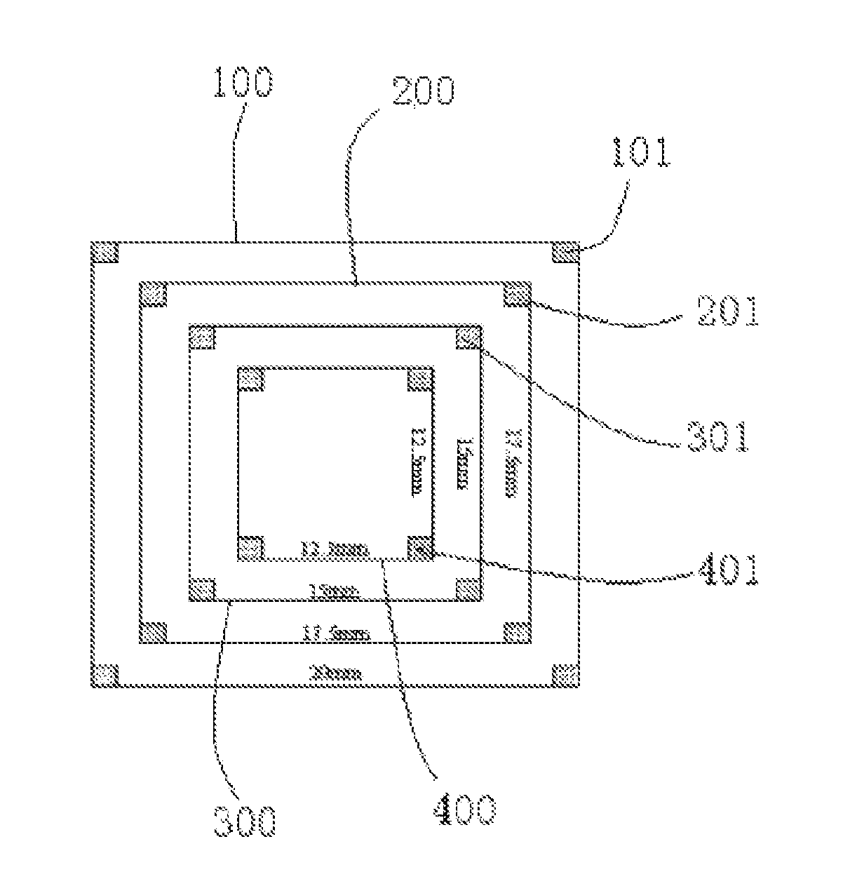
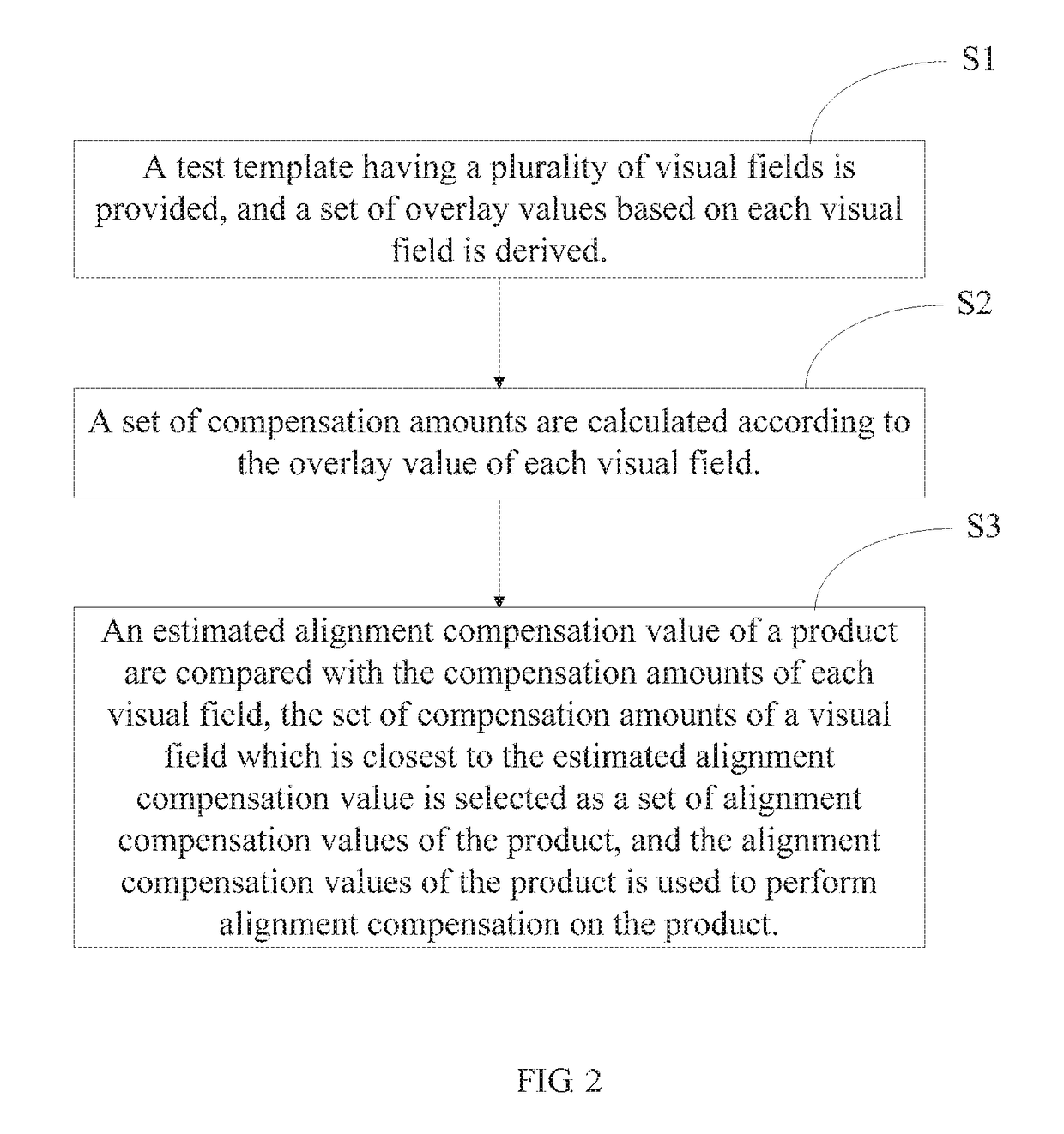
[0013]Referring to FIG. 2, FIG. 2 is a flow chart of a method for aligning and monitoring a photolithography stepper in accordance with an embodiment. Referring also to FIG. 3, FIG. 3 is an aligning and monitoring view of a photolithography stepper in accordance with an embodiment. The aligning and monitoring method of a photolithography stepper includes the following steps:

[0014]In step S1, a test template having a plurality of visual fields is provided, and a set of overlay values based on each visual...


PUM


Abstract

A lithography stepper alignment and control method, comprising: providing a test template having a plurality of field sizes, and deriving a set of overlay values for each field size (S1); calculating a set of compensation amounts for the overlay value of each field size (S2); and, comparing alignment compensation values for a product with each compensation amount for each field size, selecting as the product alignment compensation values the set of compensation amounts of a field size closest to estimated alignment compensation values, and, using the product alignment compensation values to perform alignment compensation on said product (S3).

Description


Claims


Application Information

Patent Timeline
Owner CSMC TECH FAB2 CO LTD
Why Eureka
Try Eureka