Vacuum generator device

Active Publication Date: 2017-07-20
PIAB
View PDF0 Cites 2 Cited by
  • Summary
  • Abstract
  • Description
  • Claims
  • Application Information

AI Technical Summary

Benefits of technology

[0016]Through this embodiment there is provided a dual-state valve that switches between the two positions, lower and higher, of flo

Problems solved by technology

Even if the firstly mentioned solution typically provides a reasonable fast release, this solution may however in some applications be too rough when fragile objects are concerned.
In such applications the skilled person is typically limited to use the last mentione

Method used


Image

  • Vacuum generator device
  • Vacuum generator device
  • Vacuum generator device

Examples


Example

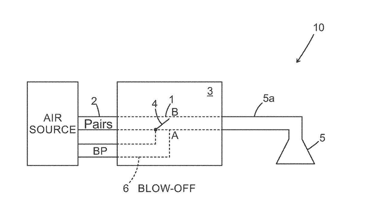
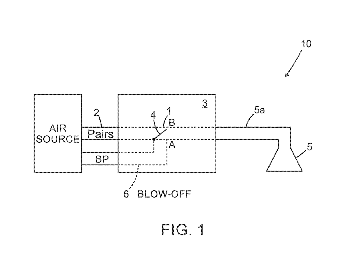
[0023]For a general description of implementation of the invention in a vacuum system 10, reference is initially made to FIG. 1. In FIG. 1, the line Pair source represents the direction of compressed air flow from a compressed air supply source AIR SOURCE via a line 2 to a vacuum generator 3 and a compressed air supply connection 6 to the same vacuum generator device 3 provided for so-called “blow-off”. The air supply source AIR SOURCE is typically the same both for supplying compressed air flow Pair source for vacuum as well as compressed air for blow-off BLOW-OFF, but via different supply connections, via line 2, or compressed air supply connection 6, respectively. The vacuum generator 3 supplies vacuum to a vacuum gripper means 5, via a suction line 5a. A valve 4 arranged in a vacuum flow connection 1 is typically switched between an opened A, and a closed position B, respectively, but may also be adjustable for a proportional control of the vacuum flow.

[0024]The vacuum generator...


PUM


Abstract

A vacuum generator (3) driven by compressed air flow and arranged to supply vacuum (VaC) to a vacuum gripper means, wherein a vacuum flow connection (1) is associated with the vacuum generator (3) and arranged to be brought in flow connection (VaC) with the vacuum gripper means in order to supply vacuum to the vacuum gripper means in result of the compressed air flow, wherein the flow connection (1) in addition comprises a second connection (8) arranged to supply a compressed air flow to the vacuum gripper means, and wherein the flow connection (1) comprises a valve (4) which is actuated by a spring force in a lower position (A) and to open said connection (1) to the vacuum gripper means and arranged to close the connection (1) in result of an air pressure from a compressed air flow (BP) in the second connection (8) in a higher position (B).

Description

TECHNICAL FIELD[0001]The present disclosure relates to a vacuum generator device that is driven by compressed air in order to generate a negative pressure applicable for vacuum cups or similar devices.BACKGROUND[0002]The present invention relates generally to material handling systems and, more particularly, to vacuum generator for vacuum cup assemblies of material handling systems that are engaged with the objects and substantially sealed thereto via operation of a vacuum source or pneumatic device connected to the vacuum devices. It is known to provide a material handling system that includes vacuum cups or the like that are adapted to be moved into engagement with an object, such as a substantially flat object or panel or the like, and to lift and move the object to a desired location. Such vacuum cups or suction cups may be moved into engagement with the object, and a vacuum source may be actuated to create a vacuum between the object and the cup such that the object is retained...

Claims


Application Information

Patent Timeline
IPC IPC(8): B25J15/06
CPCB25J15/0625B25J15/0658F04F5/20B66C1/0268F04F5/52B25J15/0675
Inventor RICKHARDSSON, FREDRIKNILSSON, JONAS
Owner PIAB
Why Eureka
Try Eureka